Installation – Lincoln Electric IM852 CV ADAPTER User Manual
Page 11
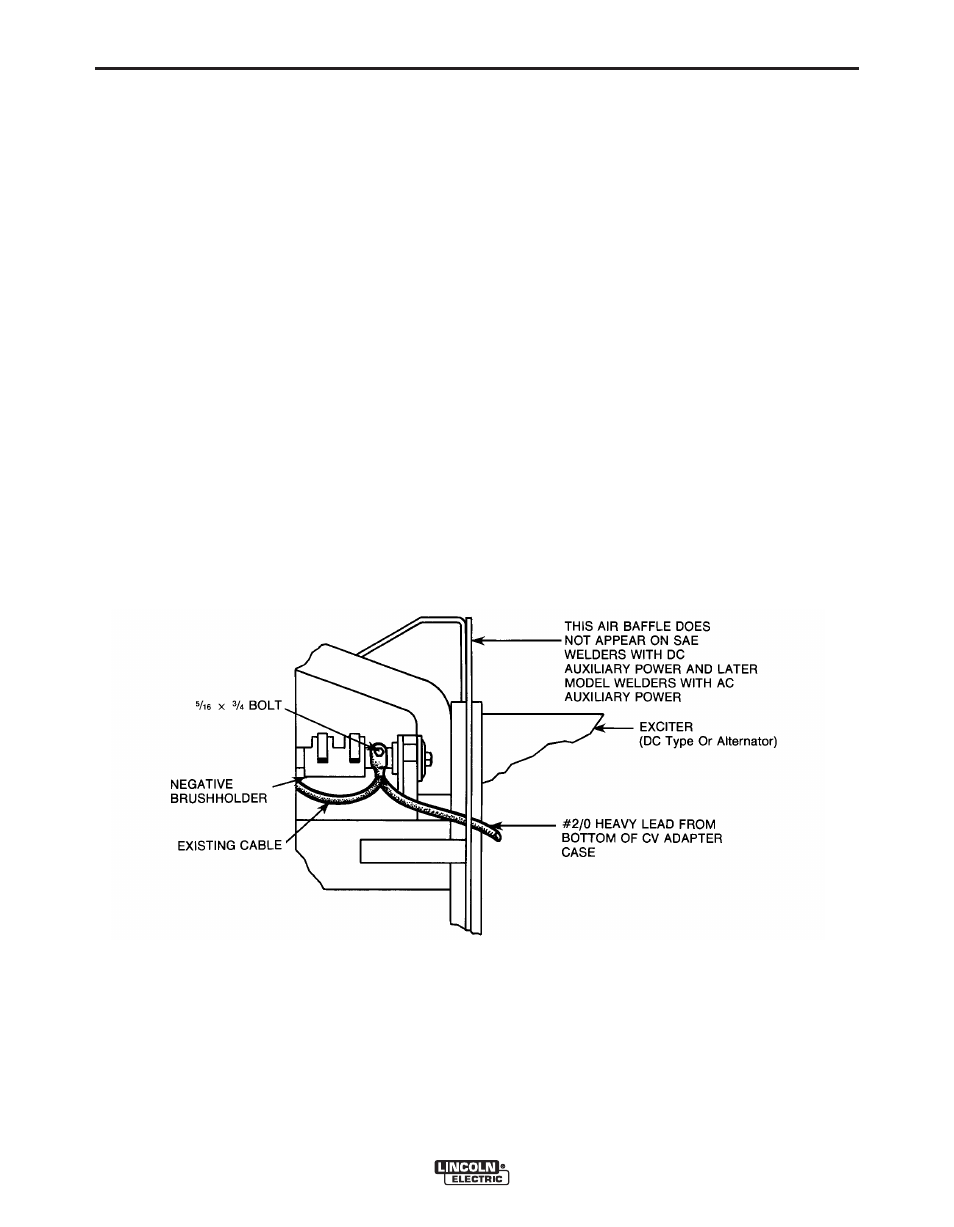
FIGURE 14 – View of Negative Generator Brushholder after Bracket cover is Removed.
A-4
INSTALLATION
CV ADAPTER
A-4
8. Connect CV Adapter lead 610 to same terminal on
polarity switch where the existing black lead is
connected.
9. Separate the white flashing diode lead from the
white hour meter lead at the taped junction (the
flashing diode is mounted on the side of the reac-
tor box located behind the control panel). Connect
the CV Adapter leads 611 to the white flashing
diode lead, 612 to the white hour meter lead, and
tape off lead 613. Insulate all screw connections
with tape.
10. Connect CV Adapter lead marked “Neg” to the
back of “Electrode” output terminal. Connect CV
Adapter lead marked “Positive” to the back of “To
Work” output terminal. Tape leads to generator
lead bundle for support.
11. Tape CV Adapter control cable leads to lead bun-
dle to secure control cable.
NOTE: FOR STEPS 12 AND 13 REFER TO FIGURES 12 AND 14.
12. The negative generator brushholder, exposed
when upper bracket cover is removed (see Figure
12), is at the 11 o’clock position when the commu-
tator is viewed from the control panel end of
welder. Remove the 5/16 bolt which connects the
existing cable to the negative brushholder. Route
the #2/0 heavy lead which exists from the bottom
of the CV adapter case as shown in Figure 14.
Obtain a 5/16 X 3/4 bolt from the hardware sent
with the CV Adapter and connect the #2/0 heavy
lead which exits from the bottom of the CV
Adapter case, along with the cable removed
above, to the negative brushholder. The #2/0
heavy lead lug should be between the existing
cable lug and the brushholder. On welders with
AC auxiliary power, tape the #2/0 heavy lead to
the alternator exciter lead bundle coming from the
alternator to support lead where possible.
13. Replace bracket cover removed in Step 1. Also,
tighten the CV Adapter which was loosely mount-
ed in Step 2. For the SAE-400 WELD’N AIR the
CV Adapter must be positioned flush against the
fuel tank rail after tightening.