Sti-6405 exit stopper with momentary reset, Sti-6403 remote horn unit installation – STI 6402WIR User Manual
Page 7
- 7 -
STI-6402 Double Door Install Notes
1. Determine length needed for reed switch
wires. STI provides 1 reed switch with 6 ft.
wires. Cut to desired length.
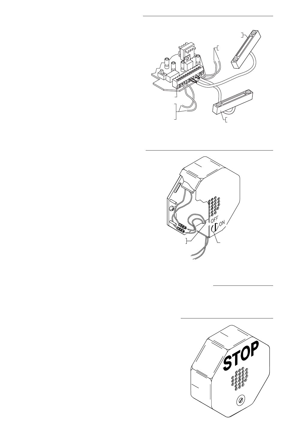
2. Connect first reed switch in RS1 and
second in RS2 (Fig. 7). (Refer to Fig. 1 for
additional details on page 4.)
3. If not using extra reed switch, add jumper
across two terminals of RS2 on terminal
block.
*Note: Alarm will sound when either door is
opened.
STI-6403 Remote Horn Install Notes
NOTE: WIRING NOT PROVIDED
NOTE: 14-24 AWG MAY
BE USED.
B
EXISTING
EXISTING
TO STI 6400 CIRCUIT
BOARD TERMINAL STRIP.
VIEW IN DIRECTION OF ARROW
REMOTE HORN WIRE CONNECTIONS
STI-6403 REMOTE HORN UNIT INSTALLATION
B
ROUTE WIRES
THROUGH NOTCH
KEY SWITCH
1. Remove cover.
2. Connect two conductor wire (14-24 AWG)
from main unit terminal block pins COM
and NO to remote horn unit terminal block.
(wire not provided). Units can be set up to
300 ft. apart. Not polarity sensitive (refer to
Fig. 1 and Fig. 7 for details).
3. Connect internal battery.
4. Mount similar to main unit with #8 x 1 in.
screws and anchors if necessary.
5. Replace cover and screws.
6. Turn key switch to ON position.
*Note: The ON/OFF key position is opposite
from 6400 main unit. Remote horn sounds
when main unit alarm is activated.
STI-6404 Double Door with Remote Horn Install Notes
The STI-6404 is a combination unit for double doors with a remote horn. Reference the installation
instructions for the main unit, the STI-6402 and the STI-6403 for complete installation.
STI-6405 Exit Stopper with Momentary Reset
The STI-6405 uses a momentary switch. After initial
installation, unit is always on and you do not have to
remember to turn it on when you leave a protected area.
This model also eliminates having to remember to re-arm it
because it is never off.
When the alarm is triggered, to silence the alarm, insert the
key and turn completely to the “RESET” position and hold
for 2 seconds, then release. The switch will spring back to
its original position and push the key out. To turn the unit
off, supply power must be removed.
RES
ET
Figure 7
Figure 8
POLYCARBONATE COVER
POLYCARBONATE BASE
120 dB HORN
ALARM DURATION
ALARM TRIP DELAY
EXIT DELAY
VOLUME
VIEW OF THE CIRCUIT BOARD
19039 SCREW
6 x 1 1/4 in.
(2) PROVIDED
19018 ANCHOR
(2) PROVIDED
BOTTOM SURFACE AS SHOWN
WIRES THROUGH NOTCH ON
AND ROUTE REED SWITCH
REMOVE FRONT COVER
VIEW SHOWING MAGNET INSTALLATION
MAGNET
NC COM NO GD
V+
RS1
RS2
KEYSW
TERMINAL BLOCK WIRING CONNECTIONS
FORM
C
DRY
CON
TACTS
RE
MOT
E
POWE
R
INPU
T
9-24
VD
C
R
EE
D
SW
ITCH
TE
R
M
IN
ALS
KE
Y
SW
ITCH
TE
R
M
IN
ALS
INTERNAL REED SWITCH
(RS1)
ALARM DURATION
ALARM TRIP DELAY
EXIT DELAY
VOLUME
VIEW OF THE CIRCUIT BOARD
MAXIMUM GAP 3/4 in. (19mm)
3/8 in. (9.5mm) ON METAL DOOR
AND FRAME
SPACERS (USE AS NECESSARY)
NOTE: 2 SPACERS UNDER BOTH
MAGNET AND REED SWITCH
MUST BE USED ON STEEL DOORS
4
3
2
1
NC
COM
NO
GD
V+
RS1
RS2
KEY
SW
SLOTS
FLANGES
TERMINAL STRIP
9 VOLT BATTERY
19011 TAMPERPROOF SCREW
(1) PROVIDED
19016 TAMPER WRENCH
(1) PROVIDED
BASE
19014 MOUNTING SCREW
(4) PROVIDED
REED SWITCH
MOUNTING LOCATIONS
(LABELED 1-4)
COVER
NC
COM
NO
GD
V+
RS1
RS2
KEY
SW
4
3
2
1
NC
COM
NO
GD
V+
RS1
RS2
KEY
SW
SLOTS
FLANGES
TERMINAL STRIP
9 VOLT BATTERY
19011 TAMPERPROOF SCREW
(1) PROVIDED
19016 TAMPER WRENCH
(1) PROVIDED
BASE
19014 MOUNTING SCREW
(4) PROVIDED
REED SWITCH
MOUNTING LOCATIONS
(LABELED 1-4)
COVER
4
3
2
1
ALARM SOUNDS WHEN DOOR IS OPENED
EMERGENCY USE ONLY
ON
OFF
NC
COM
NO
GD
V+
RS1
RS2
KEY
SW
SLOTS
FLANGES
TERMINAL STRIP
9 VOLT BATTERY
19011 TAMPERPROOF SCREW
(1) PROVIDED
19016 TAMPER WRENCH
(1) PROVIDED
BASE
19014 MOUNTING SCREW
(4) PROVIDED
REED SWITCH
MOUNTING LOCATIONS
(LABELED 1-4)
COVER
TO KEY
SWITCH
06402 REED SWITCH
(RS2)
OPTIONAL:
TO REMOTE
HORN
STI-6403
TERMINAL BLOCK
VIEW SHOWING INSTALLATION OF
ADDTIONAL REED SWITCH 06402
3/4 in. (19mm)
MAXIMUM GAP
3/8 in. (9.5mm) ON
METAL DOOR AND FRAME
MAGNET ASSEMBLY
(SEE ABOVE FOR INSTALLATION)
DOOR
SWING
6400 SWING
MAGNET
DOOR STOP
MAGNET MUST BE
INSTALLED OPPOSITE
RAISED RIB ON OUTER COVER
19039 SCREW
6 x 1 1/4 in.
(2) PROVIDED
SPACERS - USE
AS NECESSARY
NOTE: (2) SPACERS MUST BE
USED ON STEEL DOORS
19018 ANCHOR
(2) PROVIDED
MAGNET
6400 UNIT
DOOR
SWING
JAM
DOOR STOP
DOOR
TYPICAL FLUSH MOUNT DOOR JAM
INSTALLATION
TYPICAL RECESSED MOUNT DOOR JAM
INSTALLATION