Installation of alarm, Step 1 - mounting options, Installation of cabinet – STI 7525 User Manual
Page 4: Ount, Late or into, All without, Lectrical
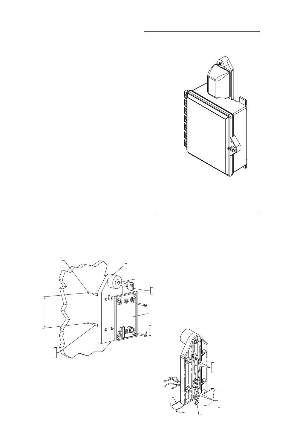
STEP 1 - MOUNTING OPTIONS
4
INSTALLATION OF ALARM
O
DRILL
3-/16 DIA HOLES
19018 ANCHOR
#8-10
(2) PROVIDED
19039 SCREW
#6 x 1 1/4 in.
(2) PROVIDED
BASE PLATE
18074 SWITCH LOCK
SUB-SA505 KEY SWITCH
MOUNTING BRACKET
3 9/32 in.
18075 REPLACEMENT
#801 KEY
O
T
O
K
EY
M
OUNT
P
LATE OR INTO
W
ALL WITHOUT
E
LECTRICAL
B
OX
ENCLOSURE
ROUTE THE TWO KEY
SWITCH WIRES THROUGH
THE HOLE AS SHOWN
WIRE ACCESS HOLE
ROUTE THE TWO REED
SWITCH WIRES FROM
CABINET THROUGH THE
HOLE AS SHOWN
E
INSTALLATION OF CABINET
1. Insert the (4) 06298 mounting tabs fully into
back box mounting tab slots. Use rubber mallet
if necessary.
2. After selecting a suitable location, place cabi-
net in closed position, against the wall. Mark
and drill (4) 1/4 in. diameter holes. Insert the
(4) 19033 anchors. Mount cabinet by driving
in the four #10 x 1 1/2 in. screws.
Note: Installation of cabinet
should be before instal-
lation of alarm because
the mounting bracket
butts up to cabinet.