Switch settings, Circuit board set-up, Warnings warranty information specifications – STI 7533 User Manual
Page 2: Safety technology international, inc, Safety technology international (europe) ltd, Alarm circuit board set-up, Sti-usa, View b
SWITCH SETTINGS
Volume - High (105 dB) at 1 ft.
ON*
Volume - Low (95 dB) at 1 ft.
OFF
Duration - 30 Second Alarm
OFF
OFF
Duration - 180 Second Alarm
OFF
ON
Duration - Continuous Alarm
ON*
OFF*
Duration - Annunciator Mode
ON
ON
Trip - Immediate
OFF*
Trip - 15 Second Delay
ON
Arming - Immediate
ON*
Arming - 15 Second Delay
OFF
FEATURE
JP2
JP3
JP4
JP5
JP7
*Factory Settings
Note: Slide black lever to desired ON/OFF
position as labeled on circuit board.
Printed in USA
Safety Technology International, Inc.
2306 Airport Road • Waterford, Michigan 48327-1209
Phone: 248-673-9898 • Toll Free: 800-888-4784
Fax: 248-673-1246 •
www.
sti-usa
.com
Safety Technology International (Europe) Ltd.
Unit 49G Pipers Road • Park Farm Industrial Estate • Redditch
Worcestershire • B98 0HU • England • Tel: 44 (0) 1527 520 999
Fax: 44 (0) 1527 501 999 • Freephone: 0800 085 1678 (UK only)
E-mail: [email protected] • Web: www.sti-europe.com
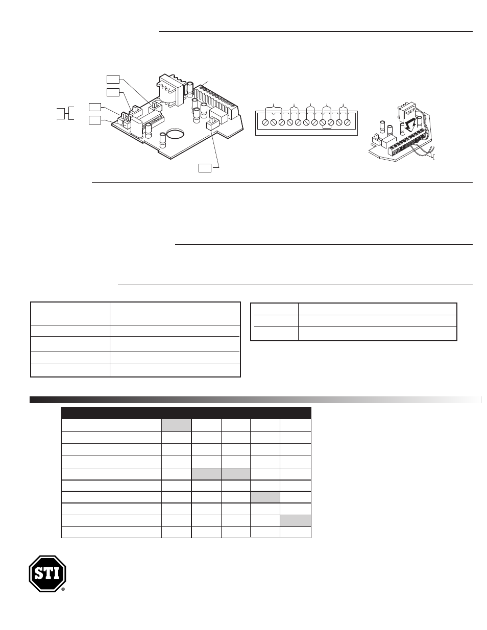
CIRCUIT BOARD SET-UP
Nex
JP5
JP2
JP4
JP3
JP7
ALARM VOLUME SWITCH
TRIP DELAY SWITCH
ARMING SWITCH
(FACTORY DEFAULT SETTINGS)
(ON)
(ON)
(OFF)
(OFF)
(OFF)
ALARM CIRCUIT BOARD SET-UP
ALARM
DURATION
SWITCH
TERMINAL BLOCK
D
(
Inst. Sht. 7532, 7533, &7533AED, JAN2014
WARNINGS
WARRANTY INFORMATION
SPECIFICATIONS
All units are recommended for indoor use. Unit must be tested periodically to verify the life of battery. STI recommends you change the battery twice a year. Duracell
MN 1604 or equivalent recommended. Installer may need to purchase a simple audio-meter, typically available at your local electronics store, to measure the sound
in areas where the alarm is expected to be heard during normal noise environment. Results from this test may prove it beneficial to purchase an additional alarm.
When purchasing a remote unit (STI-6403) you will need to periodically test the connections to make sure audibles function at a sound level to alert staff. Maximum of
three STI-6403 may be used in parallel. All specifications and information shown are current as of publication and subject to change without notice.
· Three year guarantee against breakage of polycarbonate in normal use (one year on electro mechanical and electronic components).
· Electronic warranty form at www.sti-usa.com/wc14.
9 VDC Alkaline or 9V-24VDC wired
Class II UL Listed transformer
Horn Volume at 1 ft.
95 dB low / 105 dB high
Relay Output
Form C Dry Contacts 0-30 VDC or VAC, 1 Amp
Stand by Current
10uA
Alarm Current
130mA at 95 dB / 200mA at 105 dB
Power Source
Polycarbonate Alarm Cover:
Dimensions
5.375” W x 5.375” H x 2 “ D (137mm x 137mm x 51mm)
Flammability:
UL94 V-2
Wall Thickness:
0.12 in (3.05mm)
Alarm Electronics
backbox mounting tab slots. Use rubber
mallet if necessa
in closed position, against the wall. Mark and
drill (4) 1/4 in. diameter holes. Insert the (4)
19033 anchors.
3
inst
through the access hole at
view
wires are not pinched between the wall and cabinet.
Drive in the (4) screws. Cabinet is now secure.
I
Mark and drill 3/16 in.
B
FROM MAGNETIC
CONTACT SWITCH
backbox mounting tab slots. Use rubber
mallet if necessa
in closed position, against the wall. Mark and
drill (4) 1/4 in. diameter holes. Insert the (4)
19033 anchors.
3
inst
through the access hole at
See
view Close and lock cabinet.
4
wires are not pinched between the wall and cabinet.
Drive in the (4) screws. Cabinet is now secure.
I
Mark and drill 3/16 in.
NC COM NO GD V+ RS1
RS2
KEYSW
VIEW
B
TERMINAL BLOCK WIRING CONNECTIONS
FO
R
M
C
D
R
Y
CO
N
TA
CT
S
R
EM
O
TE
P
O
W
ER
IN
P
U
T
9
-2
4
V
D
C
K
EY
S
W
IT
CH
TE
R
M
IN
A
LS
M
A
G
N
ET
IC
C
O
N
TA
CT
TI
C
R
EE
D
S
W
IT
CH
JU
M
P
ER
VIEW B