Installation guide, Embossed programming instructions, Multliple systems – STI 6200WIR8 User Manual
Page 2: Single system
— 2 —
INSTALLATION GUIDE
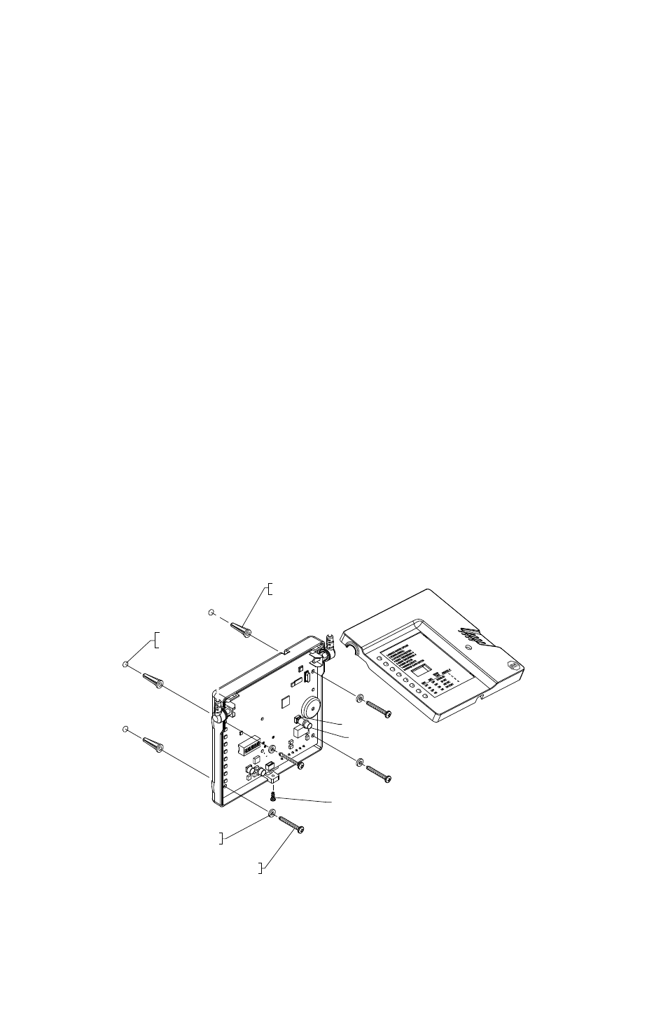
Surface Installation
1. Ensure mounting screws are removed.
2. Insert rubber feet (provided) into holes on bottom cover.
3. Route wires under the product.
Wall Mounted Installation
1. Ensure rubber feet are removed.
2. Remove front cover screw.
3. Remove cover (be careful not to lose push button).
4. Mark mounting holes on wall using bottom cover as template.
5. Drill holes with 3/16” drill bit.
6. Insert wall anchors (provided).
7. Insert power cord and wires and route on the back.
8. Insert mounting screws (provided) into plastic washers (provided).
9. Insert mounting screws into PCB holes through back of cover.
10. Insert mounting screws into wall anchors and tighten.
11. Press fit push button onto the push button switch on the circuit board.
12. Insert top cover tabs into bottom cover slots.
13. Carefully close top cover ensuring the push button inserts into cover hole and antennas rest in the side cover grooves.
14. Insert front cover screw and tighten.
15. Plug in AC adaptor.
If using for the first time or for enrollment adjustments, follow Zone Enrolling instructions. Otherwise, STI 8-CHANNEL
RECEIVER should be fully functional.
19018 ANCHOR
(4) PROVIDED
MARK AND DRILL
3/16 DIAMETER HOLES
(4) PLACES
19108 NYLON WASHER
(4) PROVIDED
19039 SCREW
(4) PROVIDED
PUSH BUTTON
19081 FRONT COVER SCREW
PUSH BUTTON SWITCH
Represents any STI 433 MHz sensor transmitting ONLY to a Master Receiver
SYSTEM 1
SYSTEM 2
MULTLIPLE SYSTEMS
Master
Receiver
Mirror #1
Receiver
Mirror #2
Receiver
Up to
1000 ft
Up to
1000 ft
Up to
1000 ft
Up to
1000 ft
Up to
1000 ft
Up to
1000 ft
Master
Receiver
Mirror #1
Receiver
Master
Receiver
Mirror #1
Receiver
Mirror #2
Receiver
- Last
Mirror #2
Receiver
- Last
Monitors Housed in a
Central Office or Location
SINGLE SYSTEM
Mirror #3
Receiver
Up to
1000 ft
Mirror #4
Receiver
- Last
Up to
1000 ft
Switches (1-8) - For reference, information is also written on the
receiver case (located under Zone ID list).
1 - MIRROR MASTER OFF/ON
2 - NORMAL/ENROLL
3 - AUTO RESTORE/LATCH
4 - SIREN TIME/MIRROR#
5 - SIREN TIME/MIRROR#
6 - CHIME OFF/ON
7 - NORMAL/DELETE
8 - MIRROR SLAVE OFF/ON
SIREN
SW4
SW5
TIME
MIRROR #
OFF
OFF
DISABLED
1
ON
OFF
30 SEC
2
OFF
ON
180 SEC
3
ON
ON
ON CONT
4
Embossed Programming Instructions:
ZONES:
LEFT BUTTON
“CALL”
RIGHT BUTTON
“RESTORE”
NO ZONE:
ON and OFF
BUTTONS
1 - MIRROR MASTER OFF/ON
2 - NORMAL/ENROLL
3 - AUTO RESTORE/LATCH
4 - SIREN TIME/MIRROR#
5 - SIREN TIME/MIRROR#
6 - CHIME OFF/ON
7 - NORMAL/DELETE
8 - MIRROR SLAVE OFF/ON
SIREN
SW4
SW5
TIME
MIRROR #
OFF
OFF
DISABLED
1
ON
OFF
30 SEC
2
OFF
ON
180 SEC
3
ON
ON
ON CONT
4
ANTENNAS
SWITCHES 1-8
ZONE LEDs
PUSH BUTTON
PIEZO
COVER
SCREW
DIPSWITCH
FUNCTIONS
WIRE ROUTE
OPTION 1
FORM C
SWITCH OUTPUTS
12V INPUTS
TERMINALS 500mA
12V OUTPUTS
TERMINALS 300mA
WIRE ROUTE
OPTION 2
TRIGGERED OUTPUT PLUG
12V , 75mA
PLUG IN ADAPTER
12V , 500mA
SURFACE FEET (x4)
(WALL MOUNTING HOLES)
EMBOSSED
INPUT AND
OUTPUTS
FCC ID: TXL34108
MODEL #34108
IC: 6335A-34108
SAFETY TECHNOLOGY INTERNATIONAL
WATERFORD, MI U.S.A.
REDDITCH, WORCESTERSHIRE UK
Tr
ig
ge
r
Ou
tp
ut
12
V
75
m
A
N
.O
.
CO
M
N
.C
.
+
1
2 V
-
I
N
50
0 m
A
30
0 m
A
PL
UG
IN
A
DA
PT
ER
12 V 500mA
ANTENNAS
SWITCHES 1-8
ZONE LEDs
PUSH BUTTON
PIEZO
COVER
SCREW
DIPSWITCH
FUNCTIONS
+
1
2 V
-
O
UT
WIRE ROUTE
OPTION 1
FORM C
SWITCH OUTPUTS
12V INPUTS
TERMINALS 500mA
12V OUTPUTS
TERMINALS 300mA
WIRE ROUTE
OPTION 2
TRIGGERED OUTPUT PLUG
12V , 75mA
PLUG IN ADAPTER
12V , 500mA
EMBOSSED
INPUT AND
OUTPUTS
FCC ID: TXL34108
MODEL #34108
IC: 6335A-34108
SAFETY TECHNOLOGY INTERNATIONAL
WATERFORD, MI U.S.A.
REDDITCH, WORCESTERSHIRE UK
Tr
ig
ge
r
Ou
tp
ut
12
V
75
m
A
N
.O
.
CO
M
N
.C
.
+
1
2 V
-
I
N
50
0 m
A
30
0 m
A
PL
UG
IN
A
DA
PT
ER
12 V 500mA
+
1
2 V
-
O
UT