Stuart Turner Jet Pump 45 PS User Manual
Page 8
- 8 -
Cont ...
3.20
Connections: The pump must be permanently connected to the fixed wiring of
the mains supply using the factory fitted supply cord, this must be a fused spur off
the ring main and
NOT connected to the boiler or the immersion heater circuits.
3.21
Wiring of connection unit:
WARNING: This appliance must be earthed.
The wires in the mains lead are coloured in accordance with the following code:
Green and Yellow: Earth
Blue: Neutral
Brown: Live
As the colours of the wires in the mains lead of this appliance may not correspond
with the coloured markings identifying the terminals in your connection unit
proceed as follows:
The wire which is coloured green and yellow must be connected to the terminal
in the connection unit which is marked with the letter E or by the earth symbol:
or coloured green or green and yellow.
The wire which is coloured blue must be connected to the terminal which is
marked with the letter N or coloured black.
The wire which is coloured brown must be connected to the terminal which is
marked with the letter L or coloured red.
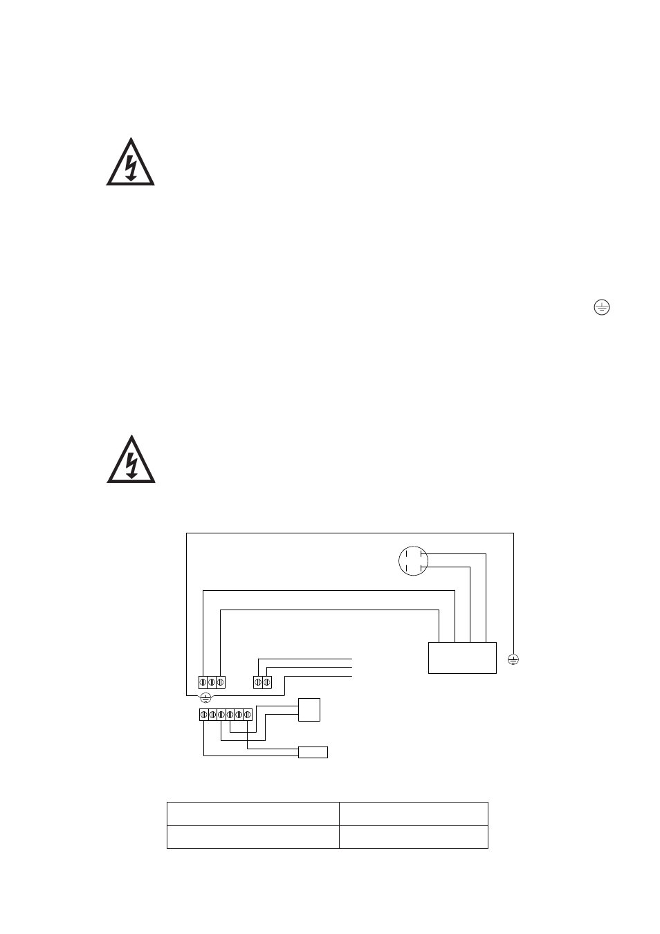
3.22
Wiring Diagram:
The supply cord and internal wiring within the terminal box are
routed and secured to ensure compliance with the electrical
standard EN 60335-1. It is essential that any disturbance of this
internal wiring is avoided and the factory routing and securing of
all internal wiring is always maintained.
Model
Fuse Size (AMPS)
All Models
13
3.23
Fuses: The following fuse size should be used with the appropriate pump:
GREEN / YELLOW
BLUE
BROWN
L
M
A
N
N
L
E
N 230 VAC/1PH/50Hz
SUPPLY
RED
CAPACITOR
MOTOR
GREEN / YELLOW (LINK WIRE)
RE
D
YELLOW
RED
BLA
CK
BLACK
FLOWSWITCH
REED (S3)
S3 S3 S2
S2
S1
S1
PRESSURE
SWITCH (S1)
Jet 55-45 PS, Jet 80-45 PS
Fig. 5