2 settings related to communication function – Yokogawa JUXTA VJU7 User Manual
Page 4
4
All Rights Reserved. Copyright © 1999, Yokogawa M&C Corporation
IM 77J01U07-01E
4th Edition Feb. 09, 2007-00
9.1.2 Input Hard Range
Select the input hard range from among AUTO, HIGH,
MIDDLE and LOW in D17: SELECT RANGE. In general, se-
lect AUTO.
●
AUTO: Sets the most appropriate input hard range auto-
matically with respect to the input range to be set.
●
HIGH: For RTD input, for a span of 130
Ω
or more in an
input range of 0 to 520
Ω
based on the reference
resistane table.
●
MIDDLE: For thermocouple or mV input, for a span of
27.5 mV or more in an input range of 10 to 100 mV con-
verted into thermoelectromotive force. For RTD input, for
a span of 38.5
Ω
or more in an input range of 0 to 176
Ω
based on the reference resistane table.
●
LOW: For thermocouple or mV input, for a span of 10
mV or more in an input range of -2.5 to 25 mV converted
into thermoelectromotive force.
NOTE
The conditions for the input hard range (HIGH,
MIDDLE and LOW) are specified for operations
within the range of accuracy rating. The input
range may be set to a range not meeting these con-
ditions, but take note of accuracy limitations. Simi-
lar accuracy limitations exist even when AUTO is
selected. For more information on accuracy limita-
tions, see the general specifications of VJU7 (GS
77J01U07-01E).
9.1.3 Input Range
Set the 0% value of input range in D22: INPUT1 L_RNG and
the 100% value of input range in D23: INPUT1 H_RNG nu-
merically within the following specified range.
Input type
Type K (CA)
Type T (CC)
Type E (CRC)
Type J (IC)
Type R
Type S
Type B
Type N
Type W3
*1
Type W5
*2
Pt100 (ITS-90)
Pt100 (IPTS-68)
JPt100 (JIS'89)
Pt50 (JIS'81)
mV signal
Operation guaranteed range
-200 to 1200
°
C
-200 to 350
°
C
-200 to 800
°
C
0 to 750
°
C
0 to 1600
°
C
0 to 1600
°
C
600 to 1700
°
C
-200 to 1200
°
C
0 to 2000
°
C
0 to 2000
°
C
-200 to 660
°
C
-200 to 660
°
C
-200 to 510
°
C
-200 to 649
°
C
-10 to 100 mV DC
Thermocouple input
RTD input
mV input
*1: W97Re3-W75Re25 (tungsten 97% rhenium 3%-tungsten 75% rhenium 25%)
The abbreviation of ASTM E988.
*2: W95Re5-W74Re26 (tungsten 95% rhenium 5%-tungsten 74% rhenium 26%)
The abbreviation of ASTM E988.
9.1.4 Direction of Output Action
When output 1 and output 2 are analog outputs, the outputs
can be reversed. Set the direction of output action in D38:
OUT1 DR (output 1) and in D39: OUT2 DR (output 2). Select
REVERSE for reverse action and DIRECT for direct action.
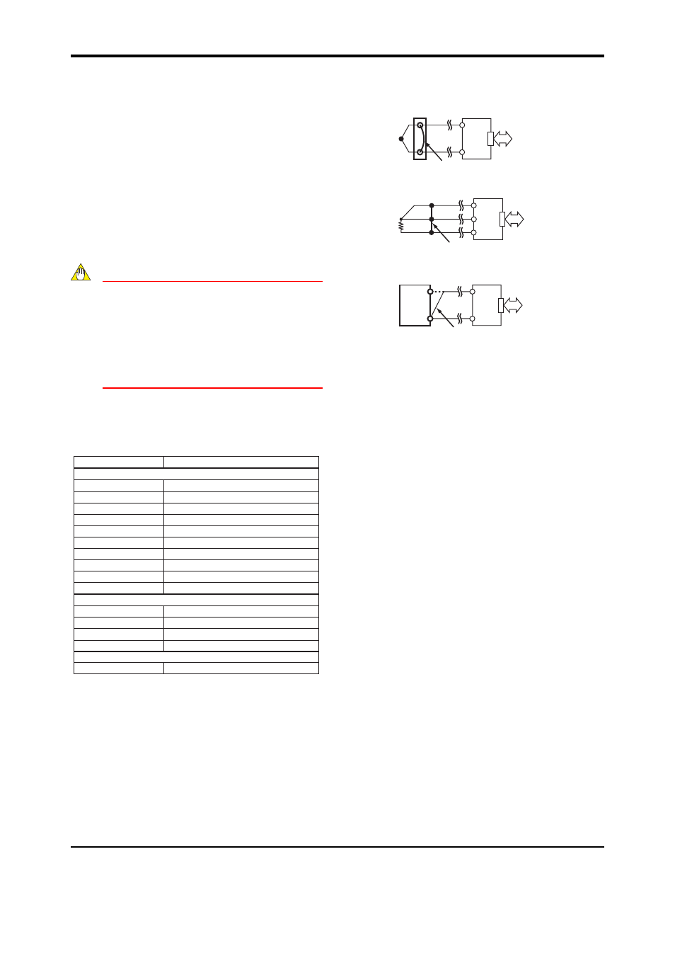
9.1.5 Wiring Resistance Correction
When an error occurs due to the influence of the input wiring
resistance, the wiring resistance can be corrected automati-
cally. Apply a stable input as shown below and select EX-
ECUTE in P01: WIRING R. The correction is also required
when the direction of burnout action is changed from UP
(DOWN) to DOWN (UP) or the wiring for input is changed.
VJ77
or
JHT200
Voltage
generator
mV Input
VJU7
Two signal lines are connected to
the same terminal of one side.
RTD Input
VJ77
or
JHT200
VJU7
Short-circuit at the cable end.
Thermocouple Input
VJU7
VJ77
or
JHT200
Short-circuit at the cable end.
9.2 Settings Related to Communication
Function
Set the following parameters when the communication func-
tion is specified for the output 2.
For more information on communication functions, see the
user’s manual for VJ Series Communication Functions (IM
77J01J11-01E).
9.2.1 Communication Protocol
Select the communication protocol from among PCLINK,
PCLINK WITH SUM, MODBUS ASCII, MODBUS RTU and
LADDER in F01: PROTOCOL.
9.2.2 Communication Address
Set the address number of the converter numerically in a
range of 1 to 99 in F02: ADDRESS.
9.2.3 Baud Rate
Select the baud rate from among 1200, 2400, 4800 and
9600 bps in F03: BAUD RATE.
9.2.4 Parity
Select the parity from among NONE, EVEN and ODD in
F04: PARITY.
9.2.5 Data Length
Select the data length from among 7 bits and 8 bits in F05:
DATA LEN.
9.2.6 Stop Bit
Select the stop bit from among 1 bit and 2 bits in F06: STOP
BIT.
9.2.7 Decimal Point Position
Number of decimals of input value (setting of D register
[D0003]) can be set. Select the number of decimals from
among 0 to 5 in F07: INPUT DEC PT.