Mounting methods, Installation locations, External wiring – Yokogawa JUXTA VJU7 User Manual
Page 2: 1 wall mounting, 2 din rail mounting, 3 mounting using a multi-mounting base, 4 using a duct, Warning, Important
2
All Rights Reserved. Copyright © 1999, Yokogawa M&C Corporation
IM 77J01U07-01E
4th Edition Feb. 09, 2007-00
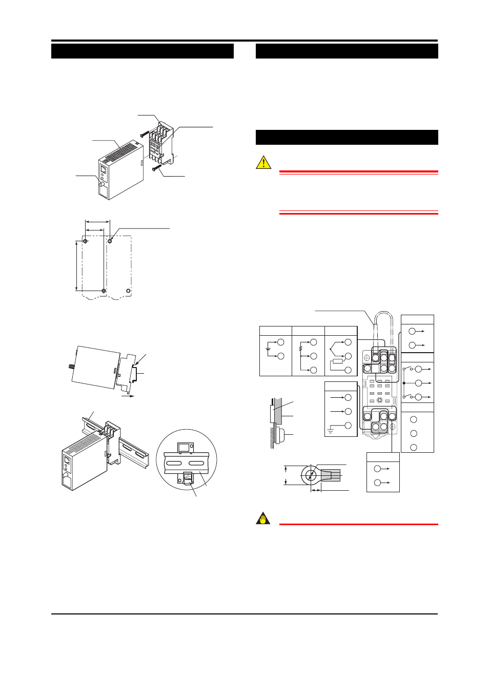
5. MOUNTING METHODS
5.1 Wall Mounting
Loosen the main unit-fixing screw to disconnect the main
unit from the socket. Next, anchor the socket onto the wall
with screws. Then, plug the main unit into the socket and se-
cure the main unit with the main unit-fixing screw.
Main
unit-fixing
screw
Socket
Main unit
Hole for main
unit-fixing screw
Mounting
screws
Unit: mm
29.5 or more
22
±
0.2
59
±
0.3
2-M4 or 2-ø4.5 or more
5.2 DIN Rail Mounting
Locate the VJU7 so that the DIN rail fits into the upper part
of the DIN-rail groove at the rear of the socket, and fasten
the socket using the slide lock at the lower part of the
socket.
DIN rail
Fit into here
Push
DIN rail
(Rear of the socket)
Slide lock
DIN rail
5.3 Mounting Using a Multi-mounting Base
For mounting using a multi-mounting base, see the user’s
manual for VJCE (VJ Mounting Base).
5.4 Using a Duct
Wiring duct should be installed at least 30 mm away from
the top and bottom faces of the main unit.
6.
INSTALLATION LOCATIONS
•
Avoid the following environments for installation locations:
Areas with vibrations, corrosive gases, dust, water, oil,
solvents, direct sunlight, radiation, a strong electric field,
and/or a strong magnetic field.
•
If there is any risk of a surge being induced into the power
line and/or signal lines due to lightning or other factors, a
dedicated lightning arrester should be used as protection
for both the product and a field-installed device.
7.
EXTERNAL WIRING
WARNING
To avoid the risk of an electric shock, turn off the
power supply and use a tester or similar device to
ensure that no power is supplied to a cable to be
connected, before carring out wiring work.
Wiring should be connected to the terminals on the socket of the
VJU7. The terminals for external connections are of M3 screws.
Use crimp-on lugs for connections to the terminals.
•
Be sure to use a compensating lead wire for thermo-
couple input.
Recommended cables: A nominal cross-sectional area
of 0.5 mm
2
or thicker for output signal cable, a nominal
cross-sectional area of 1.25 mm
2
or thicker for power
cable and shielded twisted-pair cable (AWG24) for com-
munication cable.
10
11
3
2
1
4
5
6
7
8
9
3
1
4
5
2
6
3
1
3
1
4
A
B
B
Thermocouple
RTD
mV
RJC
Input signal (Input type can be changed.)
11
10
8
GND
Power supply
9
7
Analog output
Ouptut-1
signal
5
2
Analog output
Output-2 signal
ALM1
ALM2
COM
Alarm output
5
2
6
COM
RS-485
RJC sensor
(for thermocouple input)
(NO)
(NO)
+
–
+
–
+
–
+
–
L+
N–
B+
A–
Signal
line
RJC
sensor
Terminal
screw
Recommended crimp-on lug size
(Unit: mm)
5.5 or more
ø3.2 to 3.5
Make the wiring resistance
of RTD input terminals 1
and 3 the same.
5.5 or less
IMPORTANT
●
Connect the RJC sensor at the correct position
as shown above. Otherwise tempratures cannot
be measured carrectly.
●
Conect the RJC sensor so that it overlaps the in-
put signal line.
●
Handle the RJC sensor lead wire care to prevent
disconnection.