Setting parameters, 1 front panel, 2 connecting the setting tools – Yokogawa JUXTA VJU7 User Manual
Page 3: 1 settings related to input and output
3
IM 77J01U07-01E
4th Edition Feb. 09, 2007-00
●
Use of the product ignoring the specifications
may cause overheating or damage. Before turn-
ing on the power, ensure the following:
(a)Power supply voltage and input signal value
applied to the product should meet the required
specifications.
(b)The external wiring to the terminals and wiring to
ground are as specifications.
●
Do not operate the product in the presence of
flammable or explosive gases or vapors. To do
so is highly dangerous.
●
The product is sensitive to static electricity; ex-
ercise care in operating it. Before you operate
the product, touch a nearby metal part to dis-
charge static electricity.
●
If an inductance (L) load such as auxiliary relays
or solenoid valves is used, always insert a spark
killer for diminishing sparks, such as a CR filter
or a diode in parallel with the inductance load.
Otherwise a malfunction or relay failure may oc-
cur. Refer to the following guidelines for a ca-
pacitor and resistor:
Capacitor : 0.5 to 1 mF with respect to a contact
current of 1 A
Resistor: 0.5 to 1 W with respect to a contact
voltage of 1 V
●
The power line and input/output signal lines
should be installed away from noise-generating
sources. Otherwise accuracy cannot be guaran-
teed.
●
The grounding resistance must be 100 W (JIS
Class D grounding). The length and thickness of
the grounding cable should be as short and
thick as possible. Directly connect the lead from
the ground terminal (terminal no. 8) of the prod-
uct to the ground. Do not carry out daisy-
chained inter-ground terminal wiring.
8. DESCRIPTION OF FRONT PANEL ND
CONNECTION OF SETTING OOLS
8.1 Front Panel
The communications connector on the front panel is used for
setting up parameters using a PC (VJ77 PC-based Param-
eters Setting Tool) or the Handy Terminal (JHT200). The
alarm indicator lamps for alarm 1 and alarm 2 light up if an
alarm occurs. (The alarm indicator lamps are added only
when the alarm output is specified for the output-2 signal.)
ALM1
ALM2
Alarm indicator lamp
(for alarm 1)
Communication connector
Alarm indicator lamp
(for alarm 2)
Fig. 8.1 Front Panel
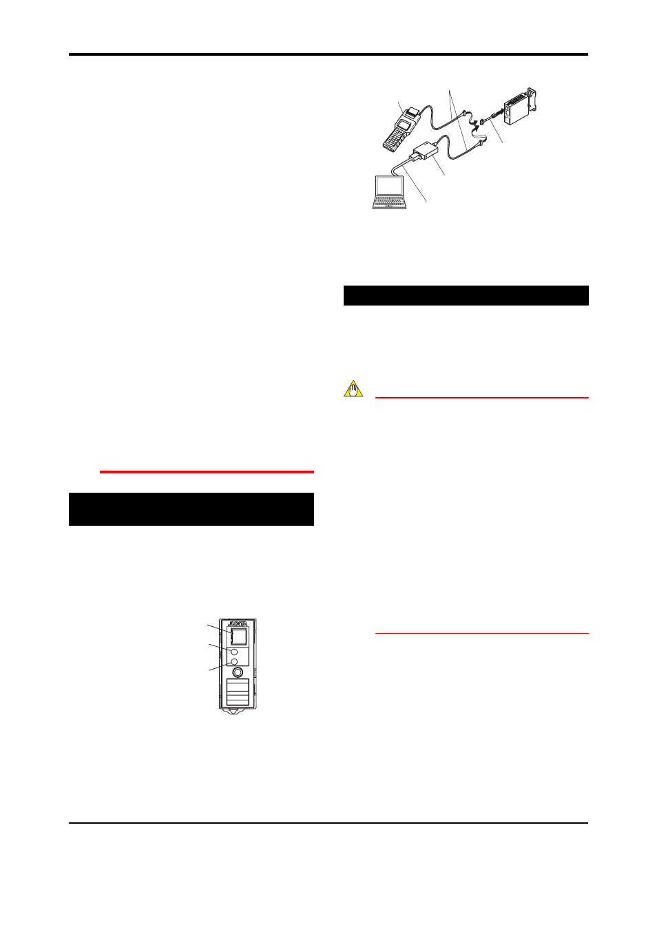
8.2 Connecting the Setting Tools
Connect the modular jack conversion adapter (E9786WH) to
the JUXTA communication cable with 5-pin connector
(F9182EE) and then connect this adapter to the communica-
tion connector of JUXTA.
JHT200
Handy Terminal
JUXTA communication cable with
5-pin connector (F9182EE)
[Comes with VJ77 and JHT200]
Modular jack conversion
adapter (E9786WH)
[Comes with VJ77]
Dedicated adapter (E9789HA)
[Comes with VJ77]
Dedicated cable (E9786WK)
[Comes with VJ77]
PC with the
VJ77 installed
Fig. 8.2 Connecting the Setting Tools
Note: The modular jack conversion adapter does not
come with the JHT200 Handy Terminal.
It is sold separately.
9. SETTING PARAMETERS
Set the parameters using a PC (VJ77 PC-based Parameters
Setting Tool) or the Handy Terminal (JHT200). Refer to the list
of parameters in this manual and the user’s manual for VJ77
PC-based Parameters Setting Tool (IM 77J01J77-01E) or
JHT200 Handy Terminal (IM JF81-02E).
NOTE
For the input sensor type, input type and tempera-
ture unit, the default values of the input range,
alarm setpoints and others are pre-defined accord-
ing to the values to be selected. Set the parameters
as follows.
1. Settings related to inputs: Set the parameters in
order starting with (1).
(1) Input sensor type
(2) Input type
(3) Temperature unit for temperature input
(4) Input hard range
(5) Input range
2. Before setting the parameters related to alarm
output and making the adjustments such as wir-
ing resistance correction and output correction,
set the parameters described in 1 above.
If setting the parameters (1) to (3) in 1 above af-
ter setting the parameters related to alarm out-
put or making the adjustment, the setpoint will
be changed or the adjustment will be reset to
the default.
9.1 Settings Related to Input and Output
9.1.1 Input Sensor Type and Input Type
Select the input sensor type in D07: SENSOR TYPE. Select
TC for thermocouple input, mV for mV input and RTD for
RTD input. When you have selected TC in D07, select the
TC type to use in D08: TC TYPE. When you have selected
RTD in D07, select the RTD type to use in D09: RTD TYPE.
Furthermore, for thermocouple or RTD input, select the tem-
perature unit in D15: UNIT.