Maintenance, Safety and emc standards, 1 calibration apparatus – Yokogawa JUXTA VJS7 User Manual
Page 5: 2 calibration procedure, Caution
5
IM 77J01S07-01E 5th Edition
Mar. 02, 2012-00
8. MAINTENANCE
The product starts running immediately when the power is turned
on; however, it needs 10 to 15 minutes of warm-up before it
meets the specified performance.
8.1 Calibration Apparatus
● 6-dial decade resistance boxes × 2 units
(Yokogawa Meters & Instruments 279301 or equivalent)
● A digital multimeter (DMM) (Yokogawa 7561 or equivalent)
● A calibrator (Yokogawa Meters & Instruments CA150 or
equivalent)
● A precision resistor of 250 Ω ±0.01%, 1W
● Setting tool for adjustment (Refer to
Communication” in this manual.)
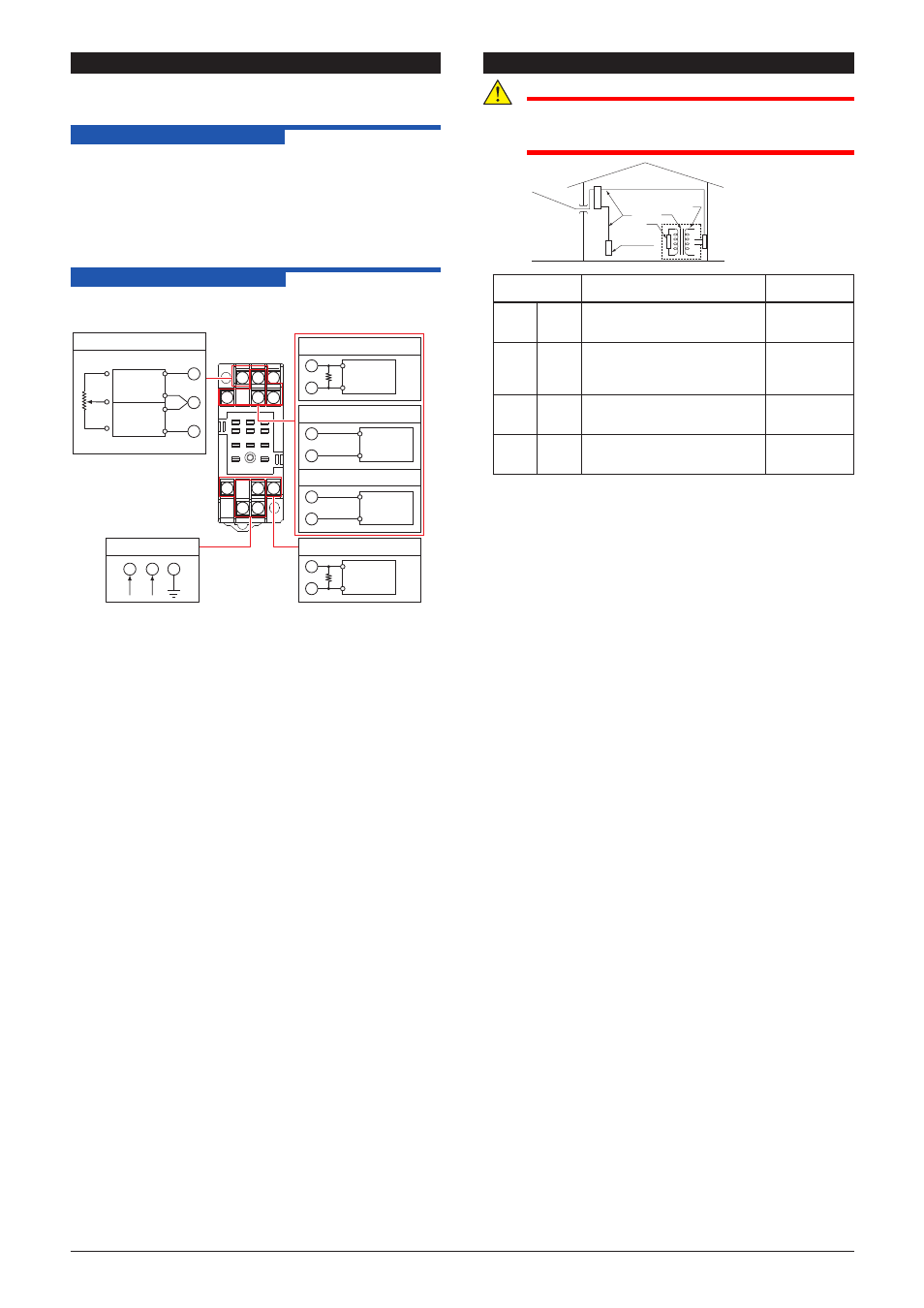
8.2 Calibration Procedure
1. Connect the instruments as shown below. First adjust the
output-1 signal and then the output-2 signal.
10
11
3 2 1
4
5
6
7
8
9
Power supply
11
10
8
L
+
N
–
GND
DMM
2
5
Output-2
R
+
–
Calibrator
2
5
Alarm-1
ALM1
COM
+
–
Calibrator
6
5
Alarm-2
ALM2
COM
+
–
DMM
7
9
Output-1
R
+
–
R: For current output using 250 Ω
precision resistor
1
4
3
Input
6 dial
variable
resistor
6 dial
variable
resistor
100%
R1
R1
R2
R2
0%
2. Operate the variable resistor according to the specifications
(total resistance, 0%, 100% resistance) of the potentiometer
to be connected. Keeping total resistance constant, change
each value of R1 and R2 to apply the resistance equivalent to
0, 25, 50, 75, and 100% of the input range to the converter.
3. Check to see the corresponding output voltages are 0, 25, 50,
75, and 100% respectively and within the specified accuracy
rating. (“R” is used for current output.)
For alarm output, check the relay action by the alarm indicator
lamp or resistance of output terminals.
● Use the setting tool (VJ77 Parameter Setting Tool or JHT200
Handy Terminal) to adjust the input/output signals.
User’s Manual for VJ77 [Document No.: IM 77J01J77-01E];
however, use the VJ77 of version R1.04 or later.
User’s Manual for JHT200 [Document No.: IM JF81-02E]
SAFETY AND EMC STANDARDS
CAUTION
This instrument is for Measurement Category I (CAT.I).
Do not use it for measurements in locations falling
under Measurement Categories II, III, and IV.
Internal Wiring
Outlet
Entrance
Cable
III
T
I
II
IV
Measurement
category
Description
Remarks
I
CAT.I For measurements performed
on circuits not directly connected
to MAINS.
II
CAT.II For measurements performed
on circuits directly connected to
the low-voltage installation.
Appliances,
portable
equipments,
etc.
III
CAT.III For measurements performed in
the building installation.
Distribution
board, circuit
breaker, etc.
IV
CAT.IV For measurements performed
at the source of the low-voltage
installation.
Overhead
wire, cable
systems, etc.
An analog input signal is measurement category I (CAT.I).
Rated transient overvoltage: 1500 V
(Note)
Note
This is a reference safety standard value for
Measurement Category I of IEC/EN/CSA/UL61010-1.
This value is not necessarily a guarantee of instrument
performance.
EMC standards: Complies with EN61326.
The above conformed instrument is only for voltage of 15 to 30
V DC.
* The instrument continues to operate at a measurement
accuracy of within ±20% of the range during testing.