Yokogawa JUXTA VJS7 User Manual
User’s manual, Model vjs7 potentiometer converter, Checking product specifications and package
User’s
Manual
1
Thank you for purchasing the JUXTA Signal Conditioner.
Please read through this manual before use for correct handling.
Network Solutions Business Division
2-9-32, Naka-cho Musashino-shi, Tokyo 180-8750 Japan
Phone: +81-422-52-7179 Facsimile: +81-422-52-6619
IM 77J01S07-01E
5th Edition Mar. 2012(YK)
CAUTIONARY NOTES FOR SAFE USE OF
THE PRODUCT
This User’s Manual should be carefully read before installing
and operating the product. The following symbol is used on the
product and in this manual to ensure safe usage.
This symbol is displayed on the product when it is
necessary to refer to the User's Manual for information
on personal and instrument safety. This symbol is
displayed in the User's Manual to indicate precautions
to avoid danger to the operator, such as an electric
shock.
The following symbols are used only in this manual.
Note
Draws attention to essential information for
understanding the operations and/or functions of the
product.
CHECKING PRODUCT SPECIFICATIONS
AND PACKAGE
(1) Checking the Model and Product Specifications
Check that the model and specifications indicated on the
nameplate attached to the main unit are as ordered.
(2) Packaged Items
Check that the package contains the following items:
• VJS7: 1
• Tag number label: 1
• Range label: 1
• User's Manual (this manual)
GENERAL
This plug-in type converter is used in combination with
transmitters which send displacement information of regulator
valves by resistance change signals from a potentiometer, and
converts the resistance change into isolated DC current or DC
voltage signals.
Output-2 can be selected from DC voltage signal, DC current
signal, communication function (RS-485), or alarm output (2
relay contacts).
Various parameters such as input range can be set and modified
using a PC (VJ77) or Handy Terminal (JHT200 and the like).
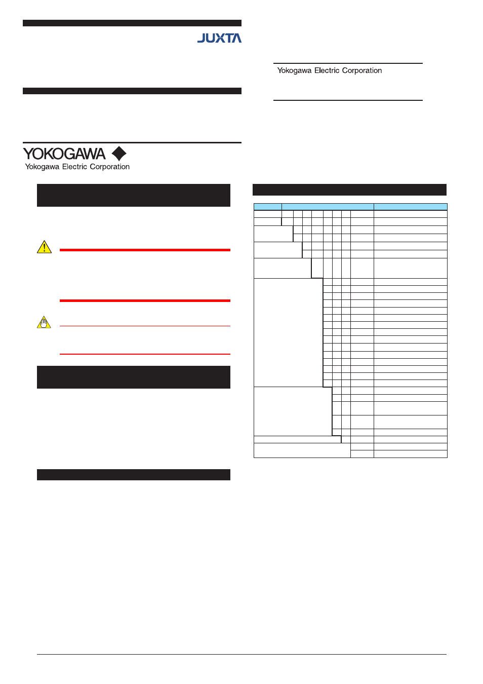
MODEL AND SUFFIX CODES
[STYLE: S1]
Model
Suffix codes
Description
VJS7
-0 □ □ -□ □ □ 0 /□□
Potentiometer Converter
-0
Always 0
Output
configuration
1
Single
2
Dual
Power supply
6
100-240 V AC/DC
(*1)
7
15-30V DC
(*2)
Input signal
-1
Potentiometer resistance
(Total resistance: 100Ω to
10kΩ)
Output-1
A
4 to 20mA DC
B
2 to 10mA DC
C
1 to 5mA DC
D
0 to 20mA DC
E
0 to 16mA DC
F
0 to 10mA DC
G
0 to 1mA DC
1
0 to 10mV DC
2
0 to 100mV DC
3
0 to 1V DC
4
0 to 10V DC
5
0 to 5V DC
6
1 to 5 V DC
7
−10 to +10V DC
Z
(Custom Order)
(*3)
Output-2
A
4 to 20mA DC
6
1 to 5V DC
P
Communication function
(RS-485)
T
High/low limit alarm output
(2 relay contacts)
N
None
0
Always 0
Options
Blank: With socket
/SN
Without socket
*1 Operating range: 85-264 V
*2 Operating range: 12-36 V
*3 DC voltage signal or DC current signal
Model VJS7
Potentiometer Converter
(Isolated Single-output and Isolated Dual-
output Types)