Description of front panel, Setting parameters, 1 front panel – Yokogawa JUXTA VJS7 User Manual
Page 3: 2 connector for communication, 1 settings related to inputs and outputs, 2 settings related to communication function, 3 settings related to alarm output
3
IM 77J01S07-01E 5th Edition
Mar. 02, 2012-00
4. DESCRIPTION OF FRONT PANEL
4.1 Front Panel
The communications connector in the front panel is used for
setting up parameters through a PC (VJ77 PC-based Parameters
Setting Tool) or the Handy Terminal. The alarm-1 and alarm-2
LEDs light up if an alarm occurs (those LEDs are provided only
when the output-2 is specified for alarm output).
Communications connector
Alarm-1 LED
Alarm-2 LED
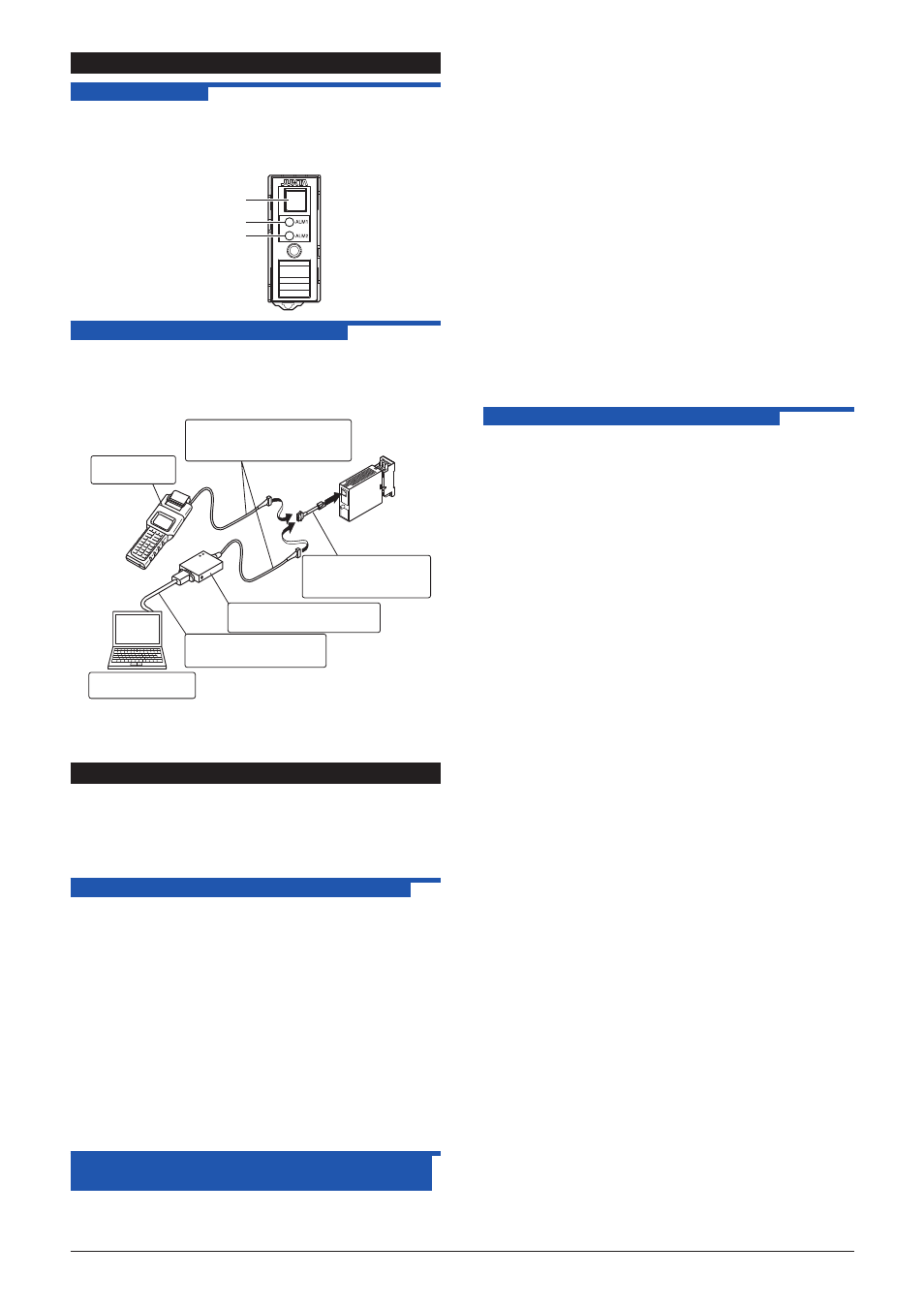
4.2 Connector for Communication
Use the connector for communication when setting the
parameters using a PC (VJ77 Parameters Setting Tool) or the
Handy Terminal
How to connect with the setting tool
Modular jack conversion
adapter (E9786WH)
[Provided with VJ77]
JHT200
Handy Terminal
JUXTA communication cable
with 5-pin connector (F9182EE)
[Provided with VJ77 and JHT200]
Dedicated adapter (E9789HA)
[Provided with VJ77]
PC which is installed
with the VJ77
Dedicated cable (E9786WK)
[Provided with VJ77]
● Use the VJ77 of version R1.04 or later.
● The modular jack conversion adapter does not come with the
JHT200 Handy Terminal. It is sold separately.
5. SETTING PARAMETERS
Set the parameters using a PC (VJ77 Parameter Setting Tool) or
the Handy Terminal. Refer to
“7. LIST OF PARAMETERS” in this
manual and the User’s Manual for VJ77 PC-based Parameters
Setting Tool (IM 77J01J77-01E) or the User’s Manual for JHT200
Handy Terminal (IM JF81-02E). Parameters are indicated inside
the
[ ].
5.1 Settings Related to Inputs and Outputs
5.1.1 Total resistance
Set the total resistance in
[D06: RESIST].
Setting range: 100 to 10000 Ω
5.1.2 Input Range
Set the 0% value of input range in
[D22: INPUT1 L_RNG],
and the 100% value of input range in
[D23: INPUT1 H_RNG].
5.1.3 Burnout
Set the burnout operation in
[D30: BURN OUT].
Set “OFF”, “UP”, or “DOWN.”
5.1.4 Direction of Output Action
Analog output signals can be reversed. To reverse the
signal from output-1, set
[D38: OUT1 DR] to REVERSE. For
output-2, set
[D39 OUT2 DR] to REVERSE. To return the
output-1 signal to normal, set
[D38: OUT1 DR] to DIRECT.
For output-2, set
[D39: OUT2 DR] to DIRECT.
5.2 Settings Related to Communication
Function
Set the following parameters when output-2 is specified
for communication function. For more information on the
communication function, see the Instruction Manual for VJ Series
Communication Function (IM 77J1J11-01E).
5.2.1 Communication Protocol
Set the communication protocol by selecting from among
PCLINK, PC-LINK WITH SUM, MODBUS ASCII, MODBUS
RTU, and LADDER in
[F01: PROTOCOL].
5.2.2 Communication Address
Set the address number of the isolator numerically in a range
of 1 to 99 in
[F02: ADDRESS].
5.2.3 Baud Rate
Set the baud rate by selecting from among 1200, 2400, 4800,
and 9600 bps in
[F03: BAUD RATE].
5.2.4 Parity
Select and set NONE, EVEN, or ODD in
[F04: PARITY].
5.2.5 Data Length
Select and set 7 bits or 8 bits in
[F05: DATA LEN].
5.2.6 Stop Bit
Select and set 1 bit or 2 bits in
[F06: STOP BIT].
5.2.7 Input Decimal Point Position
Number of digits of decimal places can be set.
Select and set among 0 to 5 digits in
[F07: INPUT DEC PT].
5.3 Settings Related to Alarm Output
Set the following parameters when output-2 is specified for alarm
output.
5.3.1 Alarm Setpoints
Set the alarm setpoints of alarm-1 and alarm-2 in
[E03: SET
POINT1] and [E04: SET POINT2] numerically.
• Setting range: A range of 0 to 100% of input range
• Setting resolution: 0.1%
5.3.2 Direction of Alarm Action
Select the direction of alarm-1 action and that of alarm-2
action from among HIGH ALM (high-limit alarm) and LOW
ALM (low-limit alarm) and set each in
[E05: ALM1 ACTION]
(direction of alarm-1 action) or
[E06: ALM2 ACTION]
(direction of alarm-2 action).
• To activate alarm status when input signal ≥ alarm setpoint,
select HIGH ALM.
• To activate alarm status when input signal ≤ alarm setpoint,
select LOW ALM.
5.3.3 Hysteresis
Set alarm-1 and alarm-2 hysteresis, in
[E09: HYSTERESIS1]
and
[E10: HYSTERESIS2]. Hysteresis is a value added to the
alarm setpoint in order for an alarm status to be released (to
normal) after the alarm status has been activated. The alarm
status will be released in the following conditions, depending
on the direction of alarm action.
1. *
When HIGH ALM (high-limit alarm) is set: Alarm is
released when input signal < (alarm setpoint - hysteresis).
2. *
When LOW ALM (low-limit alarm) is set: Alarm is
released when input signal > (alarm setpoint + hysteresis).
• Setting range: A range of 0 to 100% of input range
• Setting resolution: 0.1%