Description of alarm actions, List of parameters, 4 alarm on delay and alarm off delay – Yokogawa JUXTA VJS7 User Manual
Page 4: 5 direction of relay action
4
IM 77J01S07-01E 5th Edition
Mar. 02, 2012-00
5.3.4 Alarm ON Delay and Alarm OFF Delay
Set alarm-1 and alarm-2 ON delays in
[E11: ON DELAY1] and
[E12: ON DELAY2] and then alarm-1 and alarm-2 OFF delays
in
[E13: OFF DELAY1] and [E14: OFF DELAY2]. An alarm
ON delay is a delay time from the establishment of alarm
condition to alarm output; an alarm OFF delay is a delay time
from the establishment of return-to-normal condition to output.
• Setting range: 0 to 999 seconds
• Setting resolution: 1 second (Note that about 0.2 second will
be added to set time to prevent erroneous operation.)
For example, when an alarm ON delay is set to 1 second,
alarm output is generated if alarm status continues for
more than 1 second after the input value exceeds the
alarm setpoint. Further, when an alarm OFF delay is set
to 2 seconds, alarm output is released if normal condition
continues for more than 2 seconds after the input value has
returned to normal from the alarm status.
5.3.5 Direction of Relay Action
Set the direction of relay energizing in alarm-1 normal
condition and alarm-2 normal condition by selecting from
among NRM DEENERGIZED (de-energized under normal
condition) and NRM ENERGIZED (energized under normal
condition) in
[E15: RL1 ACTION] and [E16: RL2 ACTION]
and set them.
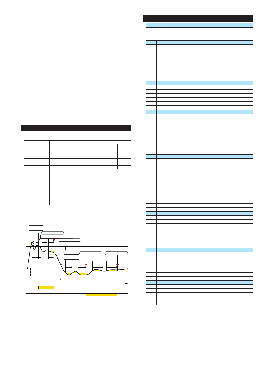
6. DESCRIPTION OF ALARM ACTIONS
This chapter describes examples of alarm actions under the
following conditions.
Item
Alarm-1
Alarm-2
Parameter
Setpoint Parameter
Setpoint
Direction of alarm
action
E05: ALM1 ACTION High-limit
alarm
E06: ALM2 ACTION Low-limit
alarm
Alarm setting
E03: SET POINT1
80%
E04 : SET POINT2
15%
Hysteresis
E09: HYSTERESIS1 10%
E10 : HYSTERESIS2 5%
Alarm ON delay
E11: ON DELAY1
1 sec.
E12 : ON DELAY2
3 sec.
Alarm OFF delay
E13: OFF DELAY1
2 sec.
E14 : OFF DELAY2 4 sec.
Description of alarm
actions
The alarm sounds if the
condition where the input value
is 80% or more of high-limit
alarm continues for more than 1
second. After the alarm sounds,
when the condition where
input value is less than 70%of
the high-limit alarm continues
for more than 2 seconds, the
status returns to normal
The alarm sounds if the
condition where the input value
is 15% or less of low-limit
alarm continues for more than
3 seconds. After the alarm
sounds, when the condition
where input value is more than
20% of the low-limit alarm
continues for more than 4
seconds, the status returns to
normal.
Alarm-1 action
Alarm-2 action
Normal
Normal
Normal
Normal
Alarm
Alarm
[%]
0
20
15
40
60
80
100
1 sec.
2 sec.
3 sec.
4 sec.
Alarm-2 hysteresis (5%)
Alarm-1 hysteresis (10%)
Alarm-1 setpoint (80%)
Alarm-2 setpoint (15%)
Elapsed time 1 sec.
[1]
[2]
[3]
[4]
[1]: Alarm status does not continue for more than 1 second after
the alarm conditions are established at alarm-1.
[2]: Normal status does not continue for more than 2 seconds after
the normal conditions are established at alarm-1.
[3]: Alarm status does not continue for more than 3 seconds after
the alarm conditions are established at alarm-2.
[4]: Normal status does not continue for more than 4 seconds after
the normal conditions are established at alarm-2.
Alarm-1
ON delay
Alarm-2
ON delay
Alarm-2
OFF delay
Alarm-1
OFF delay
Alarm conditions
established
Alarm conditions
established
Normal conditions
established
Normal conditions established
High-limit alarm ON
Low-limit alarm ON
High-limit alarm OFF
Low-limit alarm OFF
7. LIST OF PARAMETERS
Parameter Display
Item
MODEL
Model
TAG NO
Tag no.
SELF CHK
Self-check result
A
DISPLAY1
Display1
A01
INPUT1
Input value 1
A05
OUTPUT1
Output value 1
A06
OUTPUT2
Output value 2
A07
ALM1 STATUS
Alarm-1 status
A08
ALM2 STATUS
Alarm-2 status
A54
STATUS
Status
*1
A56
REV NO
Rev. no.
A58
MENU REV
MENU REV
A60
SELF CHK
Self-check result
B
DISPLAY2
Display2
B01
INPUT1
Input value 1
B05
OUTPUT1
Output value 1
B06
OUTPUT2
Output value 2
B07
ALM1 STATUS
Alarm-1 status
B08
ALM2 STATUS
Alarm-2 status
B60
SELF CHK
Self-check result
D
SET (I/O)
Setting (I/O)
*2
D01
TAG NO.1
Tag no. 1
D02
TAG NO.2
Tag no. 2
D03
COMMENT1
Comment 1
D04
COMMENT2
Comment 2
D06
RESIST
Total resistance
D22
INPUT1 L_RNG
Input low range
D23
INPUT1 H_RNG
Input high range
D38
OUT1 DR
Direction of output-1 action
D39
OUT2 DR
Direction of output-1 action
D60
SELF CHK
Self-check result
E
SET(ALM)
Setting (alarm output)
*2
E03
SET POINT1
Alarm-1 setting
E04
SET POINT2
Alarm-2 setting
E05
ALM1 ACTION
Direction of alarm-1 action
E06
ALM2 ACTION
Direction of alarm-2 action
E09
HYSTERESIS1
Alarm-1 hysteresis
E10
HYSTERESIS2
Alarm-2 hysteresis
E11
ON DELAY1
Alarm-1 ON delay setting
E12
ON DELAY2
Alarm-2 ON delay setting
E13
OFF DELAY1
Alarm-1 OFF delay setting
E14
OFF DELAY2
Alarm-2 OFF delay setting
E15
RL1 ACTION
Direction of alarm-1 relay action
E16
RL2 ACTION
Direction of alarm-1 relay action
E60
SELF CHK
Self-check result
F
SET(COM)
Setting (communication)
*2
F01
PROTOCOL
Communication protocol
F02
ADDRESS
Address
F03
BAUD RATE
Baud rate
F04
PARITY
Parity
F05
DATA LEN
Data Length
F06
STOP BIT
Stop bit
F07
INPUT DEC PT
Decimal point position of input
F60
SELF CHK
Self-check result
P
ADJUST
Adjustment
P10
ZERO ADJ1
Zero adjustment of input
P11
SPAN ADJ1
Span adjustment of input
P12
OUT1 0%
0% adjustment of output-1
P13
OUT1 100%
100% adjustment of output-1
P14
OUT2 0%
0% adjustment of output-2
P15
OUT2 100%
100% adjustment of output-2
P60
SELF CHK
Self-check result
Q
TEST
Test
Q02
OUT1 TEST
Forced output-1
Q03
OUT2 TEST
Forced output-2
Q04
ALM1 TEST
Forced output (alarm)
Q05
ALM2 TEST
Forced output (alarm)
Q60
SELF CHK
Self-check result
*1
The Status is displayed for service personnel to see history
records.
*2
There are items not displayed depending on what output-2
is specified.