4 connecting the power and energy meter and the pc, Serial communication connection – Yokogawa PR300 Power and Energy Meter User Manual
Page 8
<1. Before Using the Software>
1-5
1.4 Connecting the Power and Energy Meter and
the PC
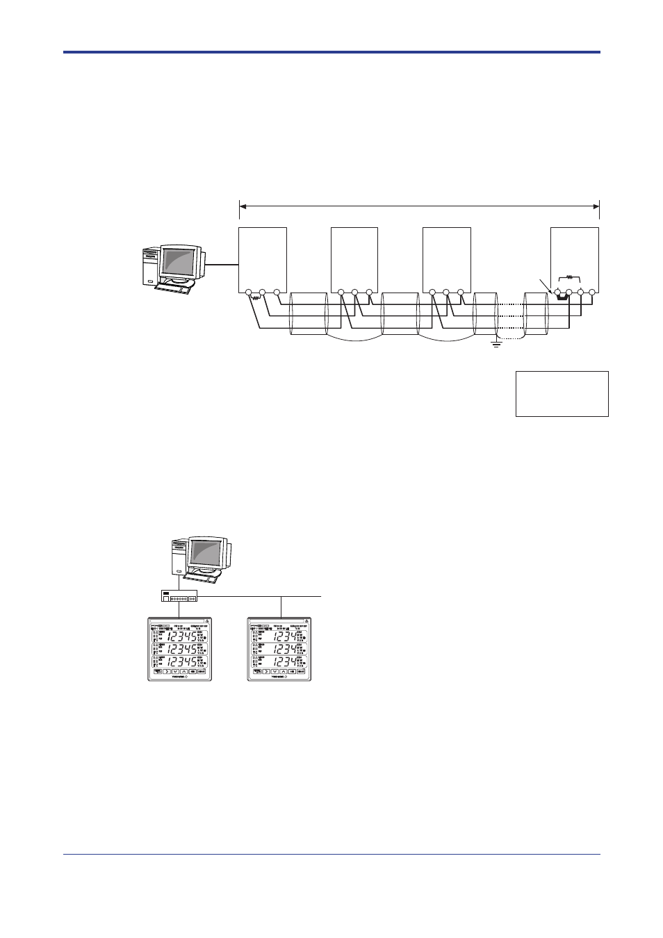
The following three methods are available for connecting the power and energy meter
and the PC.
Serial Communication Connection
(SG)
(B
+
)
(A
−
)
(B
+
)
(A
−
)
(FG)
Terminator
Short circuit
RS-485
RS-485
RS-485
Approx. 1200 m maximum (31 units maximum)
PC
ML2
RS-232C/RS-485
Converter
(Yokogawa)
RS-232C
straight
cable
PR300
UPM100
UPM101
PR300
UPM100
UPM101
PR300
UPM100
UPM101
Notes:
The PR300 employs a two-wire system for RS-485 communication.
SG: The SG terminal is connected to match the signal level of the RS-485 communication line.
FG: All shielded wires must be connected and then grounded at one place to provide noise protection for
RS-485 communication lines.
120 (built-in)
(A
−
)
(TERM)
(SG)
(SG)
(SG)
(B
+
)
(A
−
)
(B
+
)
*1
*2
*3
*1 120
Ω
externally connected (parts no.: L3035RK)
Use the resistor externally connected without using the built-in resistor of ML2.
Make resistance of the terminator the same as that of the resistor.
*2 When connecting the ML2, use it without returning an echo.
For details, refer to the ML2 RS232-C/RS-485 Converter User’s Manual (IM 77J04L02-01E).
*3 For the UPM100 and UPM101, 120
Ω
resistors are not built in.
Set the communication
method of PR300,
UPM100 and UPM101
to Modbus/RTU.
Figure1.2
Example of Serial Communication Connection
Ethernet Communication Connection (for the PR300 Only)
Ethernet
LAN
connection
HUB
IP address: 192.168.1.2
IP address: 192.168.1.3
PC
IP address: 192.168.1.1
Figure1.3
Example of Ethernet Communication Connection
IM 77C01Y01-01E