Yokogawa FU24F User Manual
Page 11
IM 12B6J8-01E-E
11
FM
Certificate no.
: 3046277
IS, Class I Div. 1, GP A, B, C, D T3…T6
Electrical data
: For sensor input circuits (by connector), connected to a
FM approved intrinsically safe apparatus meeting the entity
parameters of the SENCOM™ sensor:
Ui = 6.1 V; Ii = 230 mA; Pi = 1.2 W; Li = 4 μH; Ci = 30 μF
or
FM approved intrinsically safe Yokogawa transmitter Model
FLXA21 series.
Ambient temperature: T6 for Tamb. -40 °C to +60 °C
T5 for Tamb. -40 °C to +75 °C
T4 for Tamb. -40 °C to +85 °C
T3 for Tamb. -40 °C to +85 °C
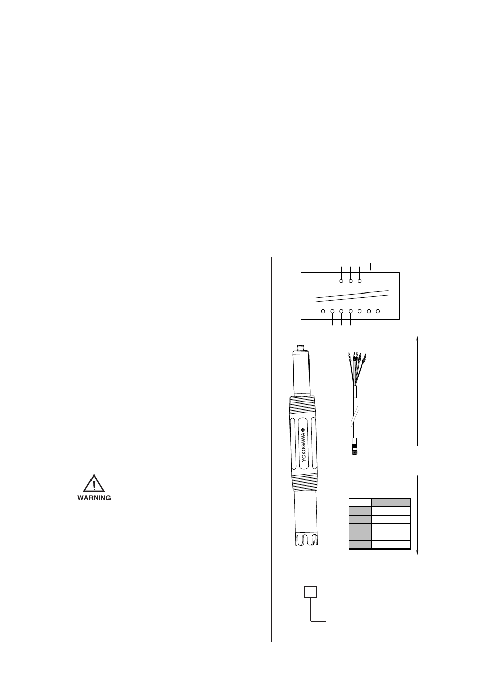
Note: Intrinsically safe when connected as per Control Drawing FF1-K1226QT (see Fig 3)
Control Drawing FM
The FU24F SENCOM
TM
sensor shall be
installed to a FM approved intrinsically safe
apparatus meeting the entity parameters
of the sensor as shown in the table as
maximum values, or to a FM certified
intrinsically safe Yokogawa transmitter
Model FLXA21 series.
When installing this equipment, follow the
manufacturer’s control drawing. Installation
should be in accordance with ANSI/ISA
RP 12.06.01 “Installation of Intrinsically
Safe Systems for Hazardous (Classified)
Locations” and the National Electrical Code
(ANSI/NFPA 70).
To prevent ignition of
flammable or combustible
atmospheres, disconnect
power before servicing or
read, understand and adhere
to the manufacturer’s live
maintenance procedures.
81 82 83 84 85 86 87
+ - G
Hazardous
location
Transmitter
WU11 cable
terminals 82-84,
86-87.
Maximum cable
length: 100 m.
Cable diameter:
5.8mm
Sensor
Ui
6.1 V
Ii
230 mA
Pi
1.2 W
Li
4 µH
Ci
30 µF
Maximum values
Fig 3: FF1-K1226QT Control Drawing FM
FU24F
Model:
NPT
Dome shape
FSM Flat surface
IS, CL I Div.1, GP A, B, C, D T3/T4/T5/T6
Ta 85 ºC/85 ºC/75 ºC/60 ºC