Yokogawa IAC-24 Integral Automatic Calibration Unit User Manual
Page 3
ISOLATE THE POWER TO ALL ELECTRICAL EQUIPMENT BEFORE WIRING THE IAC-24 AUTOCALIBRATION
SYSTEM. ELECTRICAL SHOCK MAY OCCUR IF THE POWER IS NOT ISOLATED.
1.5.1 ZR402G
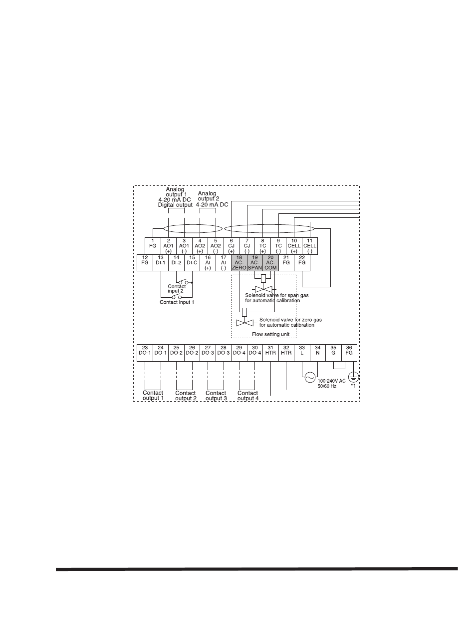
1) Attach the wires labeled Span, Zero, and Common to terminals 18,19, and 20 respectively of
the analyzer. (Fig. 2)
2) Connect the keyed electrical connector to the mating connector of the IAC-24
3) Power on the analyzer
Fig. 2
1.5.2 AV550G
1) Attach the wires labeled span, zero, and common of each IAC-24 to the AV550G corresponding
channel terminals marked span, zero, and common (Fig 3).
2) Connect the electrical connector to the bottom of the IAC-24 device
3) Power on the analyzer
3
All Rights Reserved ©Copyright March 2005, Yokogawa Corporation of America
IM 11M12D01-91E-A
Subject to change without notice.