Input circuits, 1 the signal input – Yokogawa 414 Batch Controller User Manual
Page 41
6. INPUT CIRCUITS
6.1 THE SIGNAL INPUT
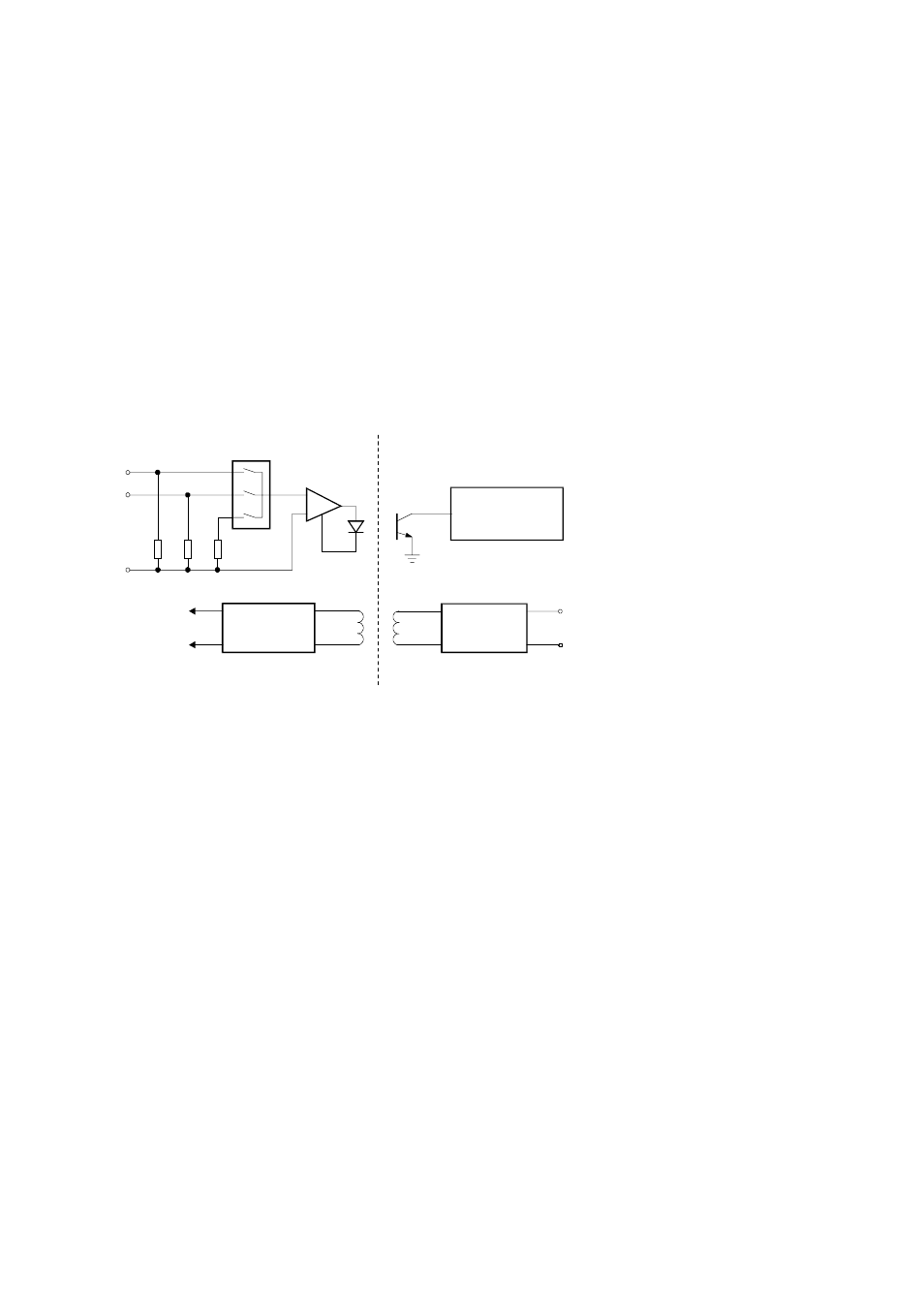
The basic circuit of the input is shown below. Both the current and voltage
signals are fed to a data selector but only one signal is processed, depending
upon whether a current (4-20mA or 0-20mA) or a voltage (1-5 V or 0-10 V)
input configuration is selected. The signal is fed to a voltage to frequency
convertor and transmitted to the microprocessor via an opto-coupler.
The microprocessor uses a crystal reference to provide an accurate measurement
of the incoming frequency. Once every 10 minutes a stable and accurate internal
reference is sampled and used to compensate the input. This technique ensures a
highly accurate measurement and makes periodic calibration unnecessary.
Input Circuits 39
Voltage to
Frequency
Microprocessor
Regulator
DC to DC
Convertor
Reference
10K
250
Ohm
Isolation
9
14
8
Voltage
Current