Yokogawa EJX930A User Manual
Page 5
Supply unit
The supply unit must be certified by a Notified
body as FISCO model and following trapezoidal or
rectangular output characteristic is used.
Uo = 14...17.5 V (I.S. maximum value)
Io based on spark test result or other
assessment,
No specification of Lo and Co is required on the
certificate or label.
Cable
The cable used to interconnect the devices needs
to comply with the following parameters:
Loop resistance Rc: 15...150 Ω/km
Inductance per unit length Lc: 0.4...1 mH/km
Capacitance per unit length Cc: 45...200 nF/km
Length of spur cable: max. 60 m (IIC and IIB)
Length of trunk cable: max. 1 km (IIC) or 5 km
(IIB)
Terminators
The terminator must be certified by a Notified body
as FISCO model and at each end of the trunk
cable an approved line terminator with the following
parameters is suitable:
R = 90 . . . 102 Ω
C = 0 . . . 2.2 µF. (0.8...1.2 µF is required in
operation)
The resistor must be infallible according to IEC
60079-11.
Number of Devices
The number of devices (max. 32) possible on a
fieldbus link depends on factors such as the power
consumption of each device, the type of cable used,
use of repeaters, etc.
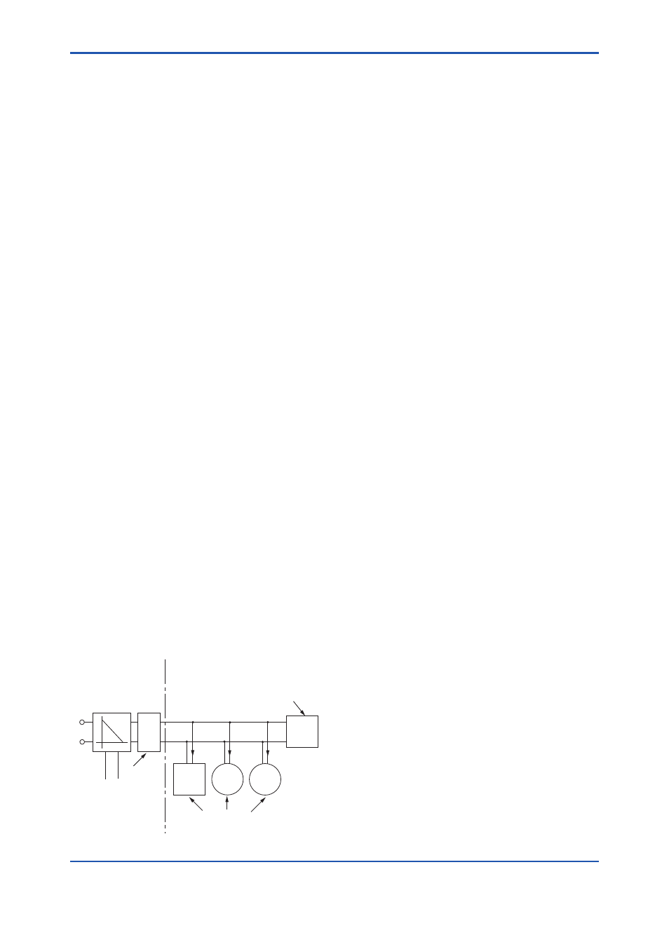
● Entity Model
Non-Hazardous
Locations
Hazardous Locations
F0206_R03.ai
Terminator
Ex i
Field Instruments
(Passive)
Hand-
held-
Terminal
Supply Unit and
Safety Barrier
Terminator
Data
U
U
I
I.S. fieldbus system complying with Entity model
I.S. values Power supply-field device:
Po ≤ Pi, Uo ≤ Ui, Io ≤ Ii
Calculation of max. allowed cable length:
Ccable ≤ Co – ∑Ci – ∑Ci (Terminator)
Lcable ≤ Lo – ∑Li
Number of Devices
The number of devices (max. 32) possible on a
fieldbus link depends on factors such as the power
consumption of each device, the type of cable used,
use of repeaters, etc.
c. ATEX Flameproof Type
Caution for ATEX flameproof type
Note 1. EJX series pressure transmitters with
optional code /KF21 for potentially
explosive atmospheres:
• No. KEMA 07ATEX0109
• Applicable Standard:
EN 60079-0:2006, EN 60079-1:2004,
EN 61241-0:2006, EN 61241-1:2004
• Type of Protection and Marking Code:
Ex d IIC T6...T4, Ex tD A21 IP6x T85, T100,
T120
• Group: II
• Category: 2G, 2D
• Enclosure: IP66 and IP67
• Ambient Temperature for gas-proof:
–50 to 75°C (T6), –50 to 80°C (T5),
and –50 to 75°C (T4)
• Maximum Process Temperature (Tp.) for
gas-proof:
85°C (T6), 100°C (T5), and 120°C (T4)
• Maximum Surface Temperature for dust-
proof:
T85°C (Tamb.: –40* to 40°C, Tp.: 85°C)
T100°C (Tamb.: –40* to 60°C, Tp.: 100°C)
T120°C (Tamb.: –40* to 80°C, Tp.: 120°C)
* –15°C when /HE is specified.
Note 2. Electrical Data
• Supply voltage: 32 V dc max.
Output current: 15 mA dc
Note 3. Installation
• All wiring shall comply with local installation
requirements.
• The cable entry devices shall be of a certified
flameproof type, suitable for the conditions of
use.