Yokogawa EJX930A User Manual
Page 3
The criterion for such interconnection is that the
voltage (Ui), the current (Ii) and the power (Pi),
which intrinsically safe apparatus can receive,
must be equal or greater than the voltage (Uo),
the current (Io) and the power (Po) which can be
provided by the associated apparatus (supply unit).
Po ≤ Pi, Uo ≤ Ui, Io ≤ Ii
In addition, the maximum unprotected residual
capacitance (Ci) and inductance (Li) of each
apparatus (other than the terminators) connected
to the fieldbus line must be equal or less than 5 nF
and 10 µH respectively.
Ci ≤ 5 nF, Li ≤ 10 µH
Supply unit
The supply unit must be certified by a Notified
body as FISCO model and following trapezoidal or
rectangular output characteristic is used.
Uo = 14...17.5 V (I.S. maximum value)
Io based on spark test result or other
assessment, No specification of Lo and Co is
required on the certificate or label.
Cable
The cable used to interconnect the devices needs
to comply with the following parameters:
Loop resistance Rc: 15...150 Ω/km
Inductance per unit length Lc: 0.4...1 mH/km
Capacitance per unit length Cc: 80...200 nF/km
Length of spur cable: max. 30 m (IIC and IIB)
Length of trunk cable: max. 1 km (IIC) or 5 km
(IIB)
Terminators
The terminator must be certified by a Notified body
as FISCO model and at each end of the trunk
cable an approved line terminator with the following
parameters is suitable:
R = 90 . . . 102 Ω
C = 0 . . . 2.2 µF. (0.8...1.2 µF is required in
operation)
The resistor must be infallible according to IEC
60079-11.
Number of Devices
The number of devices (max. 32) possible on a
fieldbus link depends on factors such as the power
consumption of each device, the type of cable used,
use of repeaters, etc.
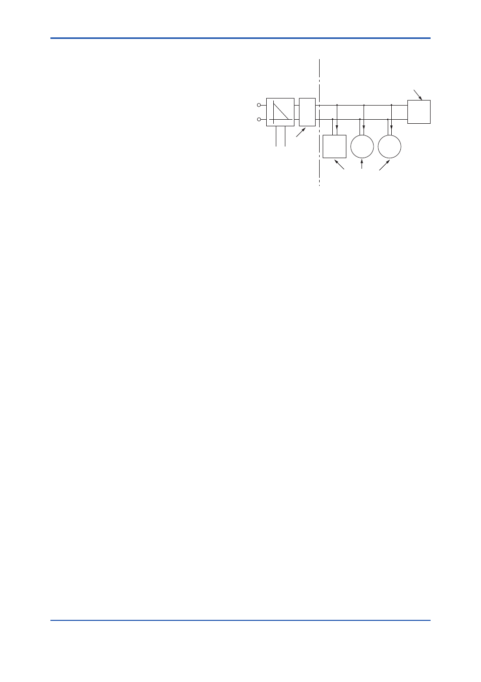
Entity Model
Non-Hazardous
Locations
Hazardous Locations
F0208.ai
Terminator
Ex i
Field Instruments
(Passive)
Hand-
held-
Terminal
Supply Unit and
Safety Barrier
Terminator
Data
U
U
I
I.S. fieldbus system complying with Entity model
I.S. values Power supply-field device:
Po ≤ Pi, Uo ≤ Ui, Io ≤ Ii
Calculation of max. allowed cable length:
Ccable ≤ Co - ∑Ci - ∑Ci (Terminator)
Lcable ≤ Lo - ∑Li
Number of Devices
The number of devices (max. 32) possible on a
fieldbus link depends on factors such as the power
consumption of each device, the type of cable used,
use of repeaters, etc.
b. ATEX Intrinsically Safe Type (for EJX90A)
Caution for ATEX Intrinsically safe type.
Note 1. EJX multivariable transmitter with optional
code /KS25 for potentially explosive
atmospheres:
• No. KEMA 06ATEX0278 X
• Applicable Standard: EN 60079-0:2006,
EN 50020:2002, EN 60079-27:2006,
EN 50284:1999, EN 50281-1-1:1998
Note 2. Ratings
[Ex ia IIC T4]
Type of Protection and Marking Code:
Ex ia IIC T4
Group: II
Category: 1GD
Ambient Temperature: –40 to 60ºC
Maximum Process Temperature (Tp.): 120ºC
Maximum Surface Temperature for dust-proof.
T85ºC (Tamb.: –40* to 60ºC, Tp.: 80ºC)
T100ºC (Tamb.: –40* to 60ºC, Tp.: 100ºC)
T120ºC (Tamb.: –40* to 60ºC, Tp.: 120ºC)
* –15ºC when /HE is specified.
Degree of Protection of the Enclosure:
IP66 / IP67