Yokogawa EJX930A User Manual
Page 4
Electrical Data
• When combined with Trapezoidal output
characteristic FISCO model IIC barrier
[Supply/Output circuit (terminals + and –)]
Ui = 17.5 V, Ii = 380 mA, Pi = 5.32 W,
Ci = 1.76 nF, Li = 0 µH
[Temperature sensor circuit]
Uo = 7.63 V, Io = 3.85 mA, Po = 8 mW,
Co = 4.8 µF, Lo = 100 mH
• When combined with Linear characteristic
barrier
[Supply/Output circuit (terminals + and -)]
Ui = 24.0 V, Ii = 250 mA, Pi = 1.2 W,
Ci = 1.76 nF, Li = 0 µH
[Temperature sensor circuit]
Uo = 7.63 V, Io = 3.85 mA, Po = 8 mW,
Co = 4.8 µF, Lo = 100 mH
[Ex ia IIB T4]
Type of Protection and Marking Code:
Ex ia IIB T4
Group: II
Category: 1GD
Ambient Temperature: –40* to 60ºC
* –15ºC when /HE is specified.
Maximum Process Temperature (Tp.): 120ºC
Maximum Surface Temperature for dust-proof.
T85ºC (Tamb.: –40* to 60ºC, Tp.: 80ºC)
T100ºC (Tamb.: –40* to 60ºC, Tp.: 100ºC)
T120ºC (Tamb.: –40* to 60ºC, Tp.: 120ºC)
* –15ºC when /HE is specified.
Degree of Protection of the Enclosure:
IP66 and IP67
Electrical Data
• When combined with Trapezoidal output
characteristic FISCO model IIB barrier
[Supply/Output circuit (terminals + and –)]
Ui = 17.5 V, Ii = 460 mA, Pi = 5.32 W,
Ci = 1.76 nF, Li = 0 µH
[Temperatura sensor circuit]
Uo = 7.63 V, Io = 3.85 mA, Po = 8 mW,
Co = 4.8 µF, Lo = 100 mH
Note 3. Installation
• All wiring shall comply with local installation
requirements. (Refer to the installation
diagram)
Note 4. Maintenance and Repair
• The instrument modification or parts
replacement by other than authorized
representative of Yokogawa Electric
Corporation is prohibited and will void KEMA
Intrinsically safe Certification.
Note 5. Special Conditions for Safe Use
• In the case where the enclosure of the
Multivariable Transmitter is made of
aluminium, if it is mounted in an area
where the use of category 1 G apparatus
is required, it must be installed such, that
even in the event of rare incidents, ignition
sources due to impact and friction sparks are
excluded.
Note 6. Installation instructions
• The test voltage for the isolation between
the intrincically safe supply/output circuit and
the frame of the apparatas for Multivariable
Transmitters that are provided with surge
protection is limited to 90 V, due to the
presence of the surge protection device only.
When used in a potentially explosive
atmosphere, requiring the use of apparatus
of equipment category 1D or 2D, certified
cable entry devices shall be used that are
suitable for the application and correctly
installed.
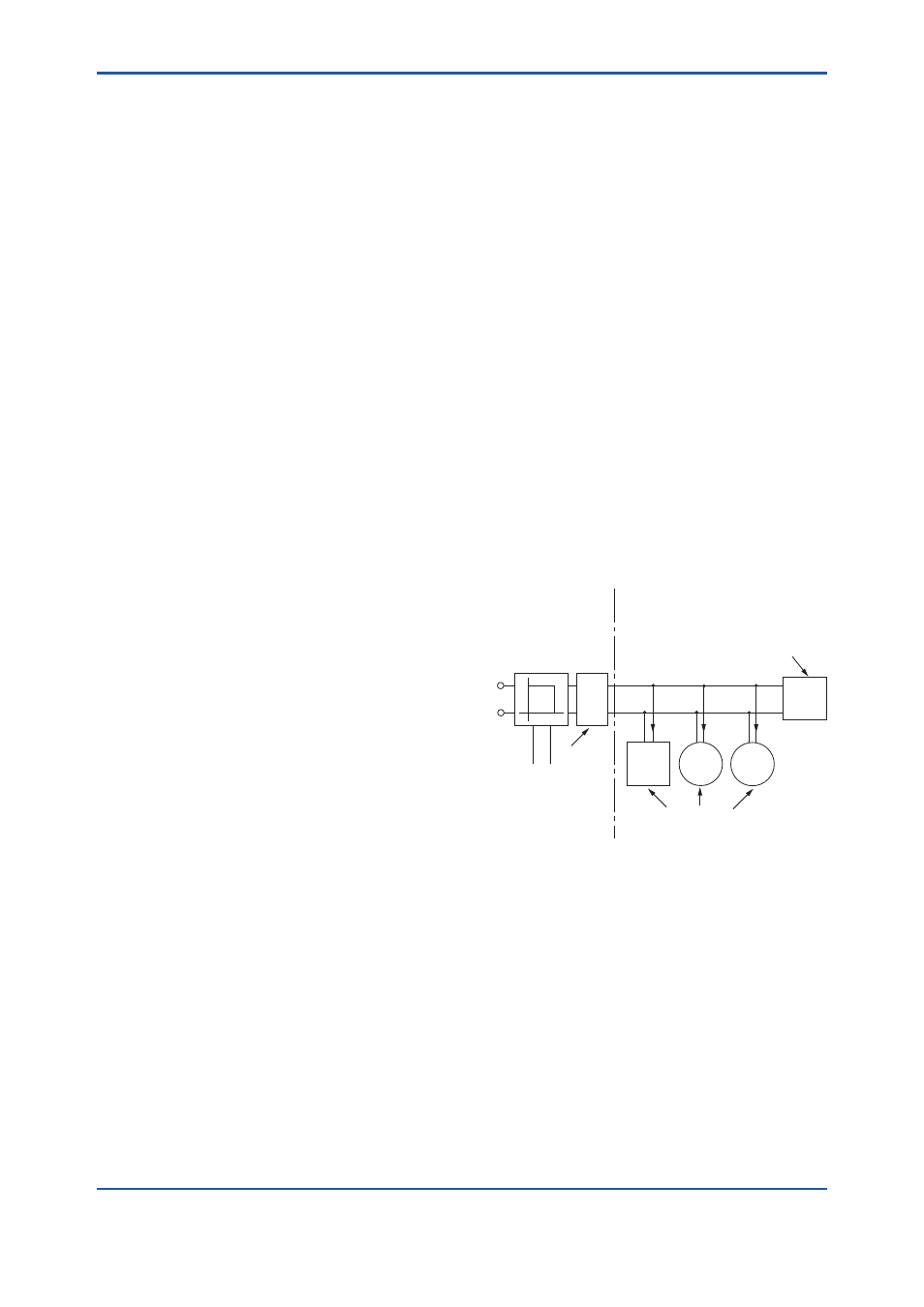
● FISCO Model
Non-Hazardous
Locations
Hazardous Locations
F0205_R03.ai
Terminator
(FISCO Model)
Ex i
Field Instruments
(Passive)
Hand-
held-
Terminal
Supply Unit and
Safety Barrier
(FISCO Model)
Terminator
Data
U
U
I
I.S. fieldbus system complying with FISCO
The criterion for such interconnection is that the
voltage (Ui), the current (Ii) and the power (Pi),
which intrinsically safe apparatus can receive,
must be equal or greater than the voltage (Uo),
the current (Io) and the power (Po) which can be
provided by the associated apparatus (supply unit).
Po ≤ Pi, Uo ≤ Ui, Io ≤ Ii
In addition, the maximum unprotected residual
capacitance (Ci) and inductance (Li) of each
apparatus (other than the terminators) connected
to the fieldbus line must be equal or less than 5 nF
and 10 µH respectively.
Ci ≤ 5 nF, Li ≤ 10 µH