5 rotating transmitter section, 6 changing the direction of integral indicator, Rotating transmitter section -4 – Yokogawa EJA110E User Manual
Page 26: Changing the direction of integral indicator -4, Important
<4. Installation>
4-4
IM 01C25B01-01E
4.5 Rotating Transmitter Section
The transmitter section can be rotated
approximately 360° (180° to either direction or
360° to one direction from the original position at
shipment, depending on the configuration of the
instrument.) It can be fixed at any angle within
above range.
1) Remove the two setscrews that fasten the
transmitter section and capsule assembly,
using the Allen wrench.
2) Rotate the transmitter section slowly and stop it
at designated position.
3) Tighten the two setscrews to a torque of 1.5
N·m.
IMPORTANT
Do not rotate the transmitter section more than
the above limit.
F0407.ai
Vertical impulse piping type
Horizontal impulse piping type
Pressure-detector section
Transmitter section
Rotate 0 to ±180° segments
Rotate 0 to ±180° segments
Transmitter section
Pressure-detector section
Conduit connection
Conduit connection
Zero-adjustment screw
Stopper
Figure 4.7
Rotating Transmitter Section (Left Side
High Pressure Type)
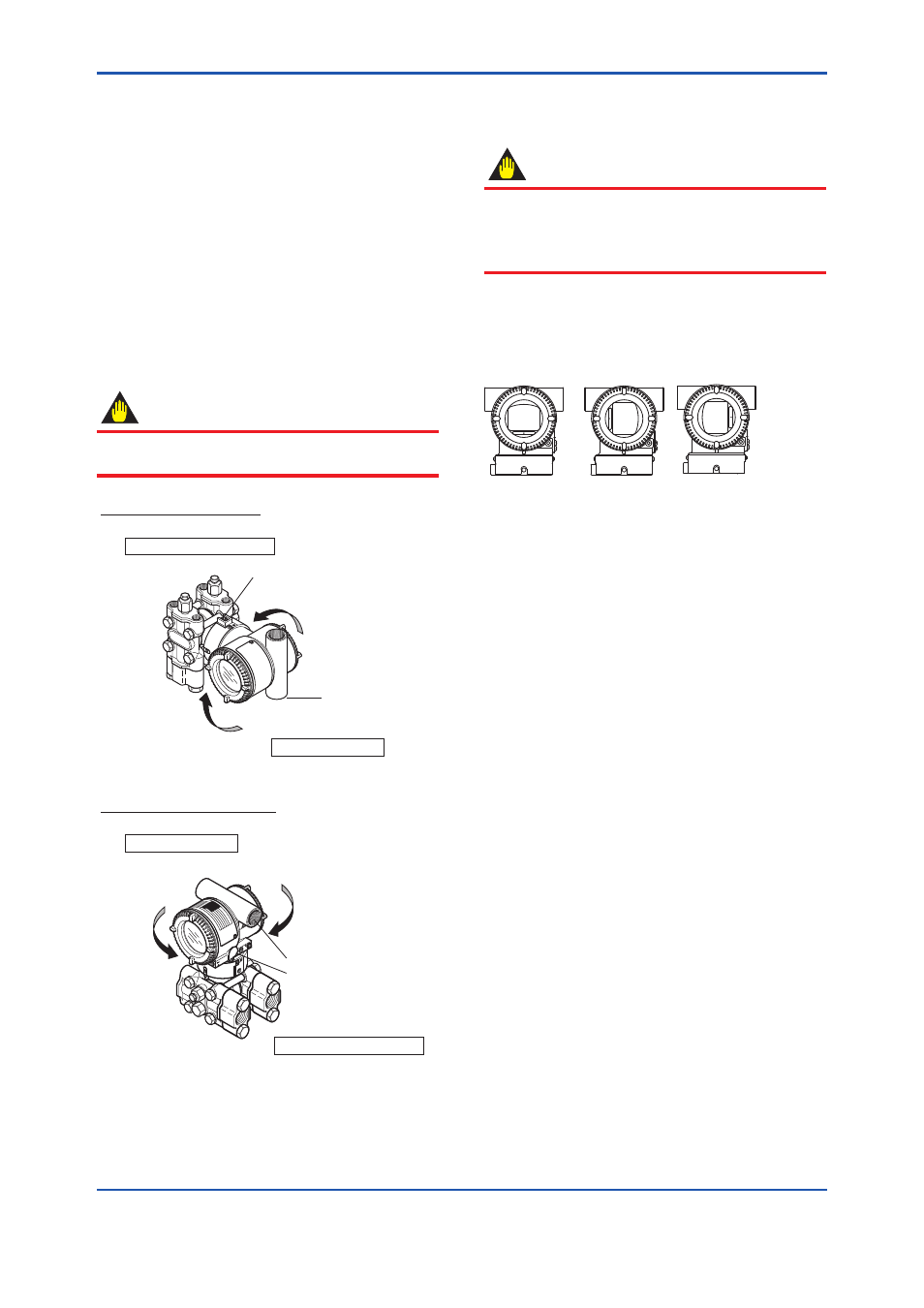
4.6 Changing the Direction of
Integral Indicator
IMPORTANT
Always turn OFF power, release pressure and
remove a transmitter to non-hazardous area
before disassembling and reassmbling an
indicator.
An integral indicator can be installed in the
following three directions. Follow the instructions in
section 8.4 for removing and attaching the integral
indicator.
F0408.ai
Figure 4.8
Integral Indicator Direction