1ø wiring,4-20ma burst (bt), 1ø wiring,4-20ma phase angle (at+), Starting out – Watlow VPAC Solid State Relay Power Control User Manual
Page 6: Single phase wiring
Starting Out
Watlow VPAC User's Manual
6
+ -
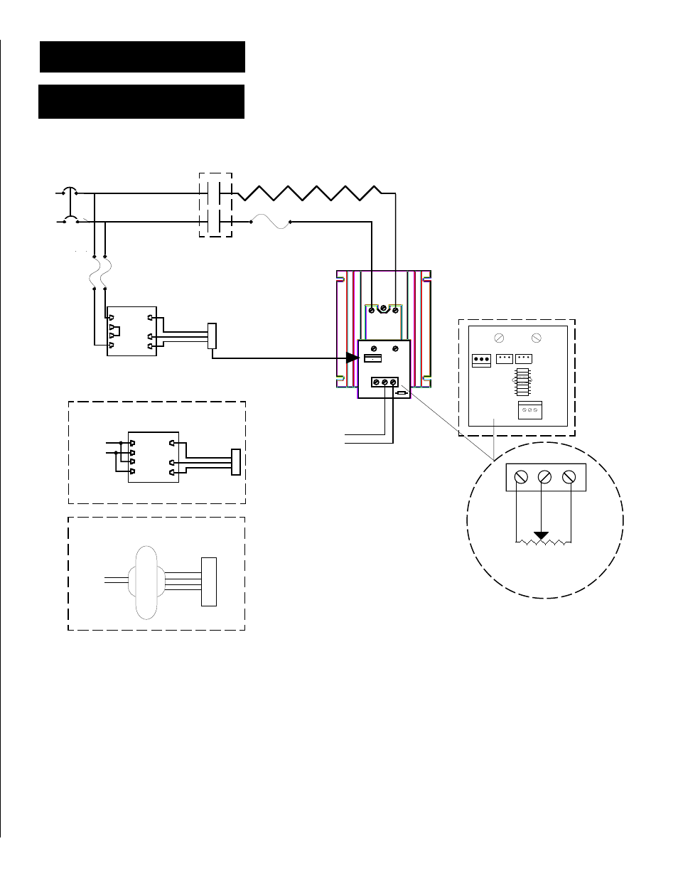
When using potentiometer input, remove
remove resistor R22 or R2 for 5K input
impedance, also for 1-5VDC input.
CW
W
CCW
NOTE: For manual control, a 1K
potentiometer may be connected to the
BT or AT+ card input terminals. Watlow
offers a kit as Manual Control Kit, part
number, 08-5362. Using this
potentiometer requires removing the
specified control card resistor for
higher impedance.
Bias and gain adjustment is required
when changing from 4-20mA input to a
manual control input or a voltage input.
Customer Supplied Wiring
240V~(ac) Power to
Transformer
4
1
4
1
24V~(ac) Power
to
AT+ or BT Card
L2-Wht
L1-Blk
L2-Wht
L1-Blk
24V~(ac) Power
to
AT+ or BT Card
Limit Contactor Contacts
(if required)
з
з
з
з
з
WARNING:
∫
∫
∫
∫
∫
2
Wiring examples show L2 in 240V~(ac)
or 480 V~(ac) configuration. In
120V~(ac) applications, L2 is neutral
and must not be fused or switched.
Failure to follow this guideline could
result in death or personal injury.
з
з
з
з
з
WARNING:
∫
∫
∫
∫
∫
1
Wiring must conform to National Electric
Code (NEC) safety standards, as well as
locally applicable codes. Failure to do
so could result in death or personal
injury, or damage to equipment.
Process +
Input -
24V~(ac) Power to
AT+ or BT Card
Single Phase Wiring
1Ø Wiring, 4-20mA Burst (BT)
1Ø Wiring, 4-20mA Phase Angle (AT+)
L2
L1
1A Fuses
Semiconductor
Fuse
R22
(300 )
L1
T1
BT
AT+
R2 (270 ) ->
˜
˜
˜
˜
˜
NOTE: The control transformer must be on the same phase as the load. See
wiring diagram above. All hot lines to the transformer should be fused at 1
Amp with the proper line voltage.
Customer Supplied Wiring
120V~(ac) Power to Transformer
Customer Supplied Wiring
277 to 480V~(ac) Power to Transformer
∫
∫
∫
∫
∫
1
∫
∫
∫
∫
∫
2
Transformer