Vpac dimensions and mounting, Maximum overall dimensions, Mounting dimensions – Watlow VPAC Solid State Relay Power Control User Manual
Page 3: Starting out
Starting Out
Watlow VPAC User's Manual
3
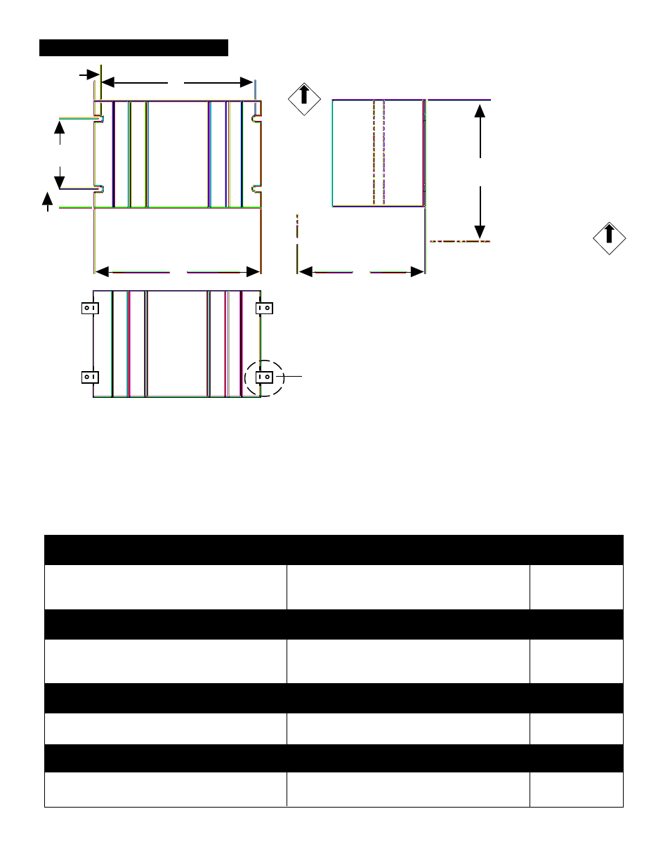
VPAC Dimensions and Mounting
з
з
з
з
з
WARNING:
∫
∫
∫
∫
∫
VPAC mounting and
spacing must conform to
local, state and national
safety codes. Failure to
conform to codes could
result in death or per-
sonal injury, or damage
to equipment.
W
D
H
A
B
C
E
UP
Maximum Overall Dimensions
Mounting Dimensions
V01 10-40A
Amps
Height (H)
Width (W) Depth (D)
A
B
C
E
Fan Cooled
10
5.60"
4.50"
1.50"
3.00"
0.50"
0.15"
4.20"
No
25
5.50"
4.75"
3.60"
2.00"
0.50"
0.15"
4.45"
No
40
6.30"
4.75"
3.60"
4.50"
0.50"
0.15"
4.45"
No
V32 10-40A
Amps
Height (H)
Width (W) Depth (D)
A
B
C
E
Fan Cooled
10
5.60"
9.00"
1.50"
3.00"
0.50"
0.15"
4.20"
No
25
5.50"
9.50"
3.60"
2.00"
0.50"
0.15"
4.45"
No
40
6.30"
9.50"
3.60"
4.50"
0.50"
0.15"
4.45"
No
V01 50-75A
Amps
Height (H)
Width (W) Depth (D)
A
B
C
E
Fan Cooled
C
50A
9.00"
*6.90"
3.50"
7.00"
N/A
N/A
5.90"
No
75A
10.50"
5.00"
5.50"
7.00"
1.00"
0.15"
4.70"
Yes
V32 50-75A
Amps
Height (H)
Width (W) Depth (D)
A
B
C
E
Fan Cooled
50A
10.50"
5.00"
5.50"
7.00"
1.00"
0.15"
4.70"
Yes
75A
10.50"
5.00"
5.50"
7.00"
1.00"
0.15"
4.70"
Yes
NOTE: *The 50Amp Single Phase width mounting dimension
includes four mounting clips (#56-0308) instead of the 1/2 round
cutouts.
NOTE: 3-Phase, 2-Leg 10-40A use 2 heat sinks for overall
dimensions.
NOTE: Mounting dimensions show maximum possible height and
depth with terminal-mounted control card attached. Unit height and
depth varies with control card configuration.
з
з
з
з
з
CAUTION:
Mount units with heat
sink fins oriented
vertically. Failure to do
so could result in unit
failure and damage to
the process.
UP