Keys and indicator lights, Watlow controls 4 ehg sl10 user’s guide, Dpu] [dpv – Watlow Series EHG SL10 Integrated Temperature Controller User Manual
Page 4: Dbu] [dbv
Watlow Controls
4
EHG SL10 User’s Guide
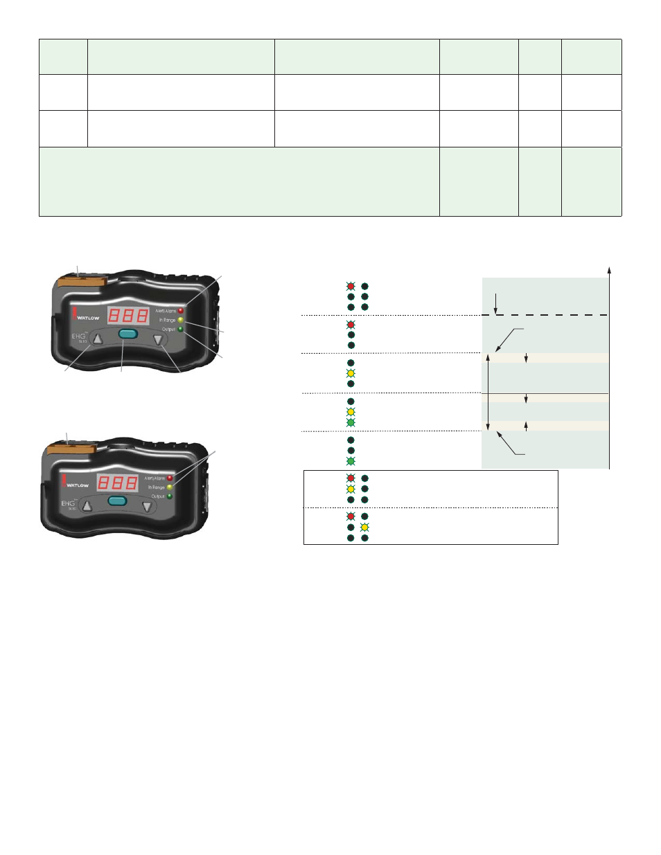
Alarm (flashing red)
Indicates that the process
temperature is higher than the
Limit High Set Point.
Alert (solid red)
Indicates that the process
temperature is higher than the
Closed Loop Set Point plus the
High Temperature Alert
Value
.
Output (green)
Indicates that the output is on.
In Range (solid yellow)
Indicates that the process
temperature is in the normal
operating range (see figure at
right).
Up-Arrow Key
Increases the
displayed value.
Down-Arrow Key
Decreases the
displayed value.
Mode Key
Toggles the display between
the set point and process
temperature. Enters edited
values and advances
to the next prompt.
Optional Communications
Connectors
Flashing
Alert/Alarm (red) and
In Range (yellow)
If they are flashing together, that
indicates an Ambient Alarm
(controller temperature higher
than 85°C).
If they are flashing alternately, that
indicates a Health Check Error.
Optional Communications
Connectors
Alert/Alarm
In Range
Output
Alert/Alarm
In Range
Output
Alert/Alarm
In Range
Output
Alert/Alarm
In Range
Output
Alert/Alarm
In Range
Output
Alert/Alarm
In Range
Output
Alert/Alarm
In Range
Output
flashing
flashing
alternate
flashing
Control
relay
LTA
HTA
relay
Safety
Alarm
relay
off off off
off off on
off on on
on on on
off off off Ambient
Alarm
[Abt] 85°C
on off on
off off off Health
Check
Error
Normal Operating Range
Limit High Set Point
[SLA]
Closed Loop Set Point plus
High Temperature Alert
Value
[HtA]
Closed Loop Set Point minus
Low Temperature Alert
Value
[LtA]
T
emper
atur
e
Alarm Hysteresis
Alarm Hysteresis
On-Off Hysteresis
[HyS]
Closed Loop Set Point
Keys and Indicator Lights
Display
Parameter Name & Description
Range
Default
Modbus
Relative
Address
Data Type
& Read/
Write
[dPu]
[dPv]
Display Prototype Version
View the interface’s prototype version.
0 to 9999
- - - -
12
unsigned
integer
R
[dbu]
[dbv]
Display Build Version
View the interface’s build number.
0 to 9999
- - - -
13
unsigned
integer
R
Note:
All values above 999 will be rounded off to fit in the three-character display. Full values can be
read with other interfaces.
Note:
The EHG SL10 does not support Modbus function code 16 (0x10) Write Multiple Registers. Pa-
rameter values must be written individually with function code 6 (0x06) Write Single Registers.
R: Read
W: Write
E: EEPROM