Eia-485, Eia-485 interface pinouts, Xon/xoff "=" command example – Watlow Series 942 Data Communications User Manual
Page 6: Mtr" command response data
6
WATLOW Series 942
How to Use Data Communications
EIA-485
EIA-485 Interface Pinouts
942A-XXXX-D000
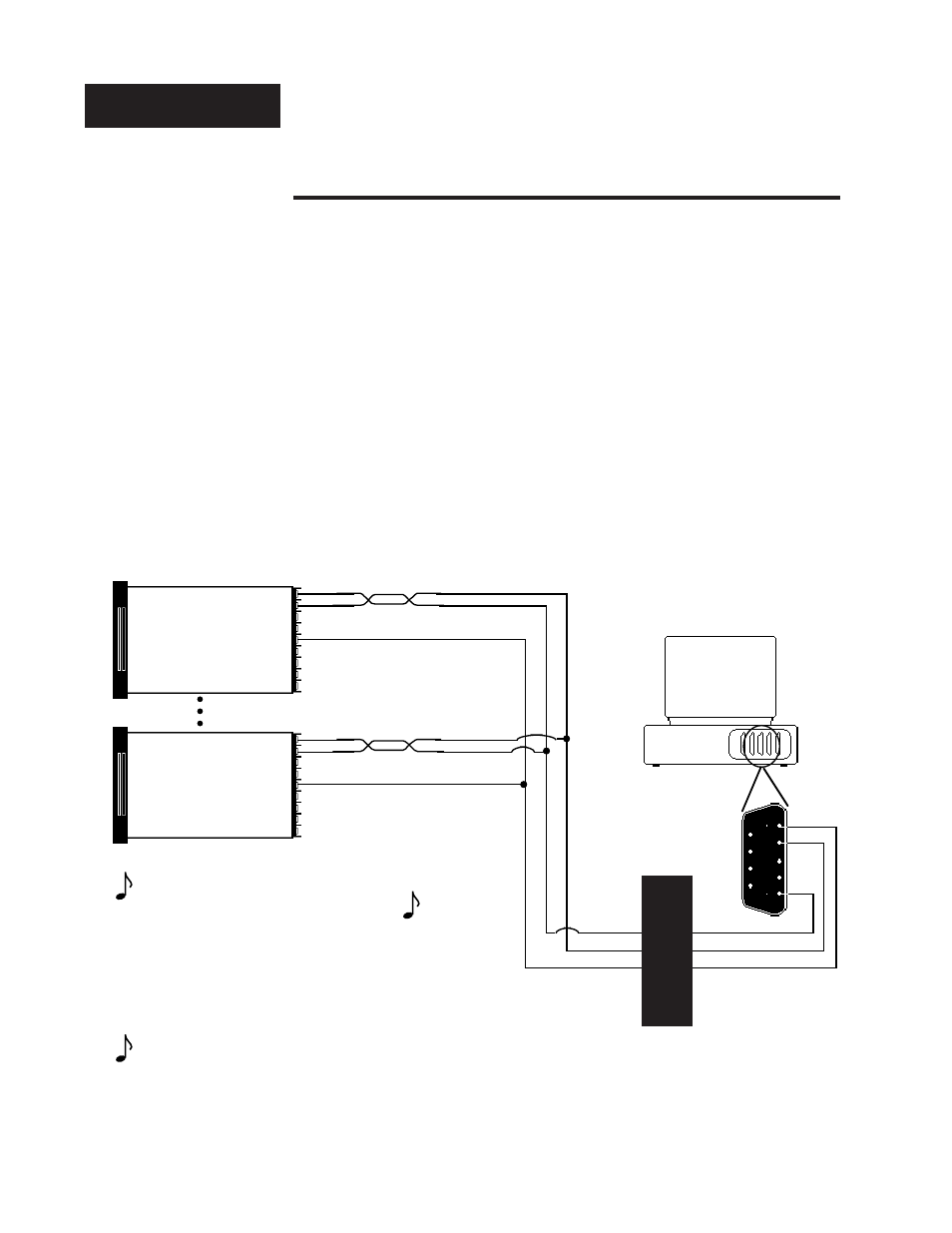
The EIA-485 communications uses a two wire (half duplex) system. There are
only two lines, both lines used for transmitting and receiving. Only one device,
the computer or the control, can be speaking at a time. There is a 5 millisec-
ond delay required for the Series 942 to go between transmission and receipt
of data. With EIA-485 you can have from one to thirty-one Series 942 controls
connected to a computer.
This diagram is a typical wiring example. The connections on the host com-
puter may vary depending on models. Refer to your computer user's manual
for more information.
T+/R+
T-/R-
Figure 3 -
EIA-485 Interface, Pin
Designations.
19
20
23
T+/R+
T-/R-
Signal Common
(Optional)
Series 945 #1
Series 945 #31
Twisted Pair Wire
1
2
3
4
5
9
8
7
6
19
20
23
Signal Common
(Optional)
Twisted Pair Wire
T+/R+
T-/R-
Com
Host Computer
(rear view)
T+/R+
T-/R-
DB-9 female
connector
(viewed from wire side)
Series 942
Series 942
Black Box Interface
See reference P.7B
NOTE:
The Electronic
Industry Association
EIA-485 standard
recommends a
maximum 4000 ft.
total network
distance.
NOTE:
DB-25 Could be
used for DB-9
depending on serial
port connector