Figure 3 — control console without a limit – Watlow Control Console User Manual
Page 7
Wa t l o w
C o n t r o l C o n s o l e
■
5
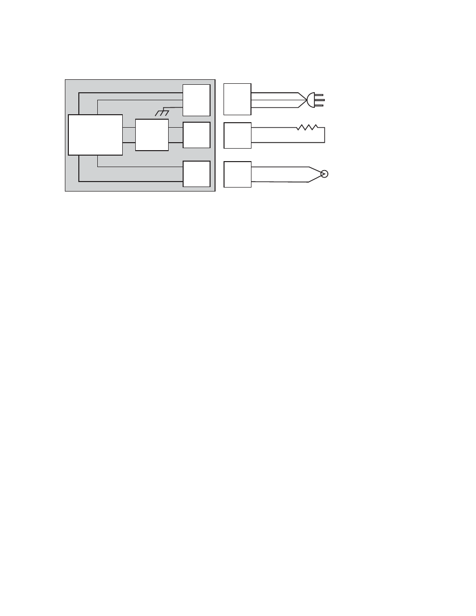
Figure 3 — Control Console without a limit.
2. Heater Connections
The heater output(s) utilizes either AMP Mate-’n’-
Lok® connector(s) or twist-and-lock connector(s).
The mating connector and terminals are provided.
To ensure proper crimping of the AMP Mate-’n’-Lok®
terminals, the proper equipment should be used.
AMP recommends using part number 90300-2 for
terminal crimping and part number 458994-2 for
extraction of the terminals from the connector.
Please consult the TYCO-AMP Corporation at 1-800-
468-2023 for further information.
3. Thermocouple Connections
Using a small screwdriver, remove the two screws
holding the cover of the male miniature thermocou-
ple connector(s). Loosen, but do not remove the +
and - terminal screws. The connector(s) can accom-
modate wire sizes up to 20-gauge, stranded wire.
Insert the red wire from the thermocouple to the (-)
terminal of the connector(s). Do not wrap the wire
around the terminal. Repeat the step for the positive
thermocouple lead.
4. Communication Connections
EIA-232 Communications
• Female DB9 connector mounted in box
• Pin 2: receive
• Pin 3: transmit
• Pin 5: common
EIA-485 Communications
• Female DB9 connector mounted in box
• Pin 2: T-/R-(A)
• Pin 3: T+/R+(B)
• Pin 5: common
* To ensure proper crimping of the DB9 terminal,
the proper equipment should be used. AMP recom-
mends using part number 58448-2.
5. Start Up
For start up and function of the temperature con-
troller, please refer to the user's manual for the
respective temperature controller that is included
with the Console.
Solid-state Relay
Power Power
Input Input
Controller
Output
Output
Vdc
Vdc
Vac
Vac
Out
Out
In
In
In
In
Ground
In
In
Ground
Out
Out
In
In
Power Cord
Output Connector
Input Connector
L1
L2
GND
Heater Element
Thermocouple