Chapter two, Installation & wiring, Pre-installation – Watlow Control Console User Manual
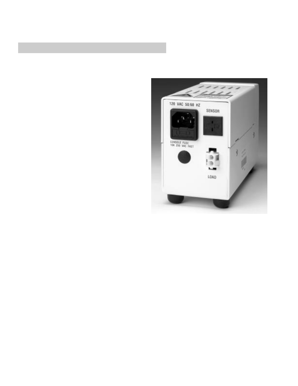
Page 6: Installation, Figure 2 — rear view of console without the, Communications option, Chapter two: installat ion & wiring
4
■
C o n t r o l C o n s o l e
Wa t l o w
Chapter Two: Installat
ion & Wiring
Pre-Installation
ç
CAUTION
High Temperature Limit: Only the Watlow Controller/Limit
console utilizes a high temperature limit control. Install
high temperature control protection in systems where an
overtemperature fault condition would present a fire haz-
ard or other hazard. Failure to install temperature control
protection where a potential hazard exists could result in
damage to equipment and property, and injury to person-
nel.
ç
WARNING
Fire Hazard: Extreme care should be taken to locate the
control console in a safe environment. Mounting the con-
trol console in atmospheres containing combustible
gasses and vapors should be avoided. According to
Article 501 of the National Electrical Code (NEC), the
maximum surface temperature of the enclosure shall not
exceed 80% of the auto-ignition of the surrounding
atmosphere when the control console is continuously
energized. Care should be taken to keep combustible
materials far enough away to be free of the effects of
high temperatures.
ç
WARNING
Heater Output. Power is applied to the heater output ter-
minals via the line cord. L1 is switched through the
solid-state relay to the connector and L2 is connected to
the heater output connector. DO NOT apply voltage to
the heater.
Installation
1. Wiring Connections
Wiring of the control consoles utilizes connections for
the thermocouple, input power and heater output.
The mating connectors are shipped with the con-
soles. It is the user's responsibility to properly size
and install feeder wire.
Refer to Figure 2 for 120V layout. Refer to Figure 3
for wiring diagram.
Figure 2 — Rear view of console without the communica-
tions option.