Frls, Flow to 205 scfm, How to order – Ross Controls FILTER_REGULATOR User Manual
Page 5
72
© 2012,
ROSS CONTROLS.
All Rights Reserved.
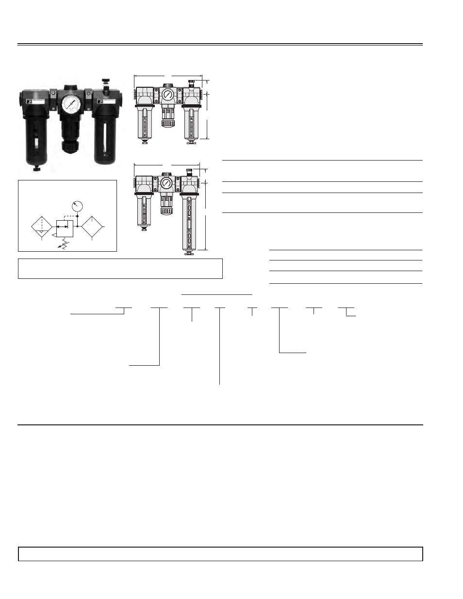
FEATURES:
• Individual filter, regulator, lubricator
• Modular or inline mounting
• 5-micron rated polyethylene filter element; optional 40-micron
element
• Aluminum bowl with clear nylon sight glass
or polycarbonate
plastic bowl with steel shatterguard
• Internal automatic filter drain; optional manual or electronic drain
• Optional extended aluminum lubricator bowl with sight glass
• Self-relieving diaphragm-type regulator; optional non-relieving
• Pressure gauge; two gauge ports
Ports: 3/8, 1/2, 3/4
Flow to 205 scfm
A
C
B
0
B A R
1 0 0 x k P a
p s i
120
1
6
0
20
0
80
4
0
0
2
4
6
8
10
12
14
Metal Bowls
A
C
B
0
B A R
1 0 0 x k P a
p s i
120
1
6
0
20
0
80
4
0
0
2
4
6
8
10
12
14
Extended Metal
Lubricator Bowl
MD4
TM
FRLs
STANDARD SPECIFICATIONS (for products on this page):
Ambient/Media Temperature:
Polycarbonate plastic bowl: 40° to 125°F (4° to 52°C).
Metal bowls: 40° to 175°F (4° to 79°C).
Bowls: 9-ounce (270-ml) capacity aluminum bowl with clear nylon
sight glass or polycarbonate plastic bowl with steel shatterguard.
Optional 15-ounce (450-ml) extended aluminum lubricator bowl with
two clear nylon sight glasses.
Bowl Rings: Nylon.
Cap Color: Gold standard; optional gray, yellow, red, blue.
Filter Drain: Internal automatic drain; optional manual drain or
electronic drain.
Filter Element: 5-micron rated polyethylene; optional 40-micron element.
Fluid Media: Compressed air.
Heads: Zinc.
Inlet Pressure:
For automatic drain model:
With polycarbonate plastic bowl: 15 to 150 psig (1.0 to 10.3 bar).
With metal bowl: 15 to 200 psig (1.0 to 13.8 bar).
For manual drain model:
With polycarbonate plastic bowl: 0 to 150 psig (0 to 10.3 bar).
With metal bowl: 0 to 200 psig (0 to 13.8 bar).
Oil Adjustment: External; tamper-resistant.
Outlet Pressure: Adjustable up to 125 psig (8.6 bar).
Pressure Adjustment Locking Key: Removable.
Pressure Gauge: 0 to 200 psig (0 to 14 bar); 1/4 NPT gauge
ports front and rear.
Seals: Nitrile.
Sight Dome: Clear nylon.
Threads: NPT standard, BSPP, SAE.
DIMENSIONS inches (mm)
Weight †
Bowl
A
B*
C
Depth †
lb (kg)
9 oz Plastic 10.9 (276) 7.7 (195) 2.2 (56) 2.9 (73) 6.94 (3.15)
9 oz Metal 10.9 (276) 7.6 (193) 2.2 (56) 3.1 (79) 6.94 (3.15)
15 oz Metal 10.9 (276) 10.6 (269) 2.2 (56) 3.1 (79) 7.13 (3.24)
* Bowl removal clearance: For 9-ounce bowls add 3.4 (86).
For extended bowl add 6.1 (155).
† Less gauge.
BOWL SIZE
53P - Two 9 oz Polycarbonate Bowls
53M - Two 9 oz Metal Bowls
53E - 9 oz metal bowl on filter
15 oz metal bowl on lubricator
53F - 9 oz polycarbonate bowl on filter
15 oz metal bowl on lubricator
REGULATOR ADJUSTMENT RANGE
A - 0-175 psig (0-12.1 bar) with 0-200 psig (0-13.8 bar) gauge
B - 0-125 psig (0-8.6 bar) standard with 0-200 psig (0-13.8 bar) gauge
C - 0-50 psig (0-3.4 bar) with 0-60 psig (0-4.1 bar) gauge
D - 0-20 psig (0-1.3 bar) with 0-60 psig (0-4.1 bar) gauge
E - no regulator with 0-60 psig (0-4.1 bar) gauge
FILTER
ELEMENT TYPE
A - 40-µm
B - 5-µm (standard)
LUBRICATOR TYPE
S - Standard
Q - Quick-Fill Cap
N - No Lubricator
ADD ON L-O-X
®
1 - Outlet Side
2 - Inlet Side
3 - L-O-X
®
with EEZ-ON
®
on Outlet Side
4 - L-O-X
®
with EEZ-ON
®
on Inlet Side
- Blank for no L-O-X
®
PIPE SIZE
3 - 3/8 NPTF
4 - 1/2 NPTF
5 - 3/4 NPTF
C - 3/8 BSPP
D - 1/2 BSPP
E - 3/4 BSPP
F - 3/4-16 SAE
G - 7/8-14 SAE
MD4
53P
B
A
5
5
2
S
*
FILTER REGULATOR TYPE
5 - Side by side (two piece) with auto drain
6 - Side by side (two piece) with manual drain
7 - Side by side (two piece) with electronic drain - manual drain only
8 - Side by side (two piece) with automatic external drain - manual drain only
COLOR
G - Gray
Y - Yellow
R - Red
B - Blue
2 - Gold (standard)
HOW TO ORDER
B
REPLACEMENT FILTER ELEMENT KIT
Element Rating/Type
Kit Number
0.5-µm polyethylene - Standard
R-A115-106PE5
40-µm bronze
R-A115-106PE3
ISO Symbol - FRL
Automatic Drain - Self-relieving
2
1
AIR FLOW DATA
See Flow Charts for individual assembly components on preceding pages.
IMPORTANT NOTE: Please read carefully and thoroughly all of the CAUTIONS on the inside back cover.
For mounting bracket options, see page 77.