Ramsey Winch HD-P8000 914184-0209 User Manual
Page 13
11
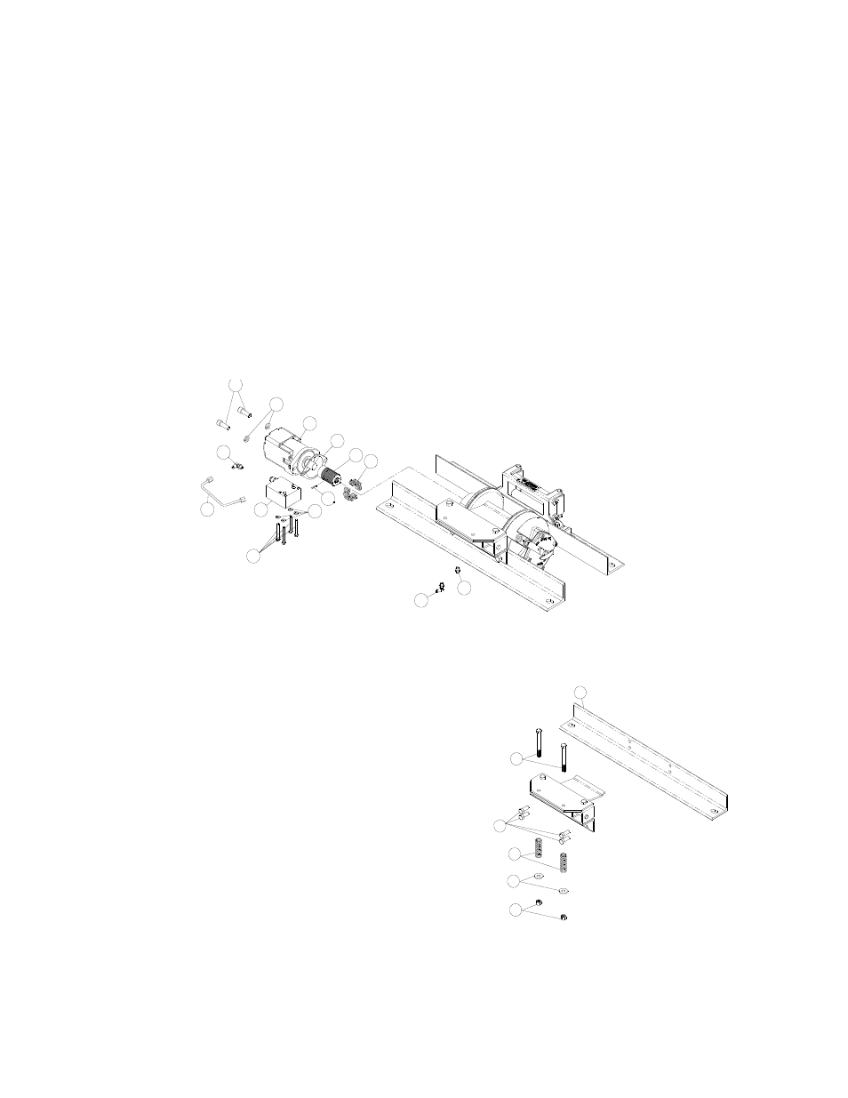
Insert springs (item #48) into pockets in back of brake piston. The two empty pockets should be on op-
posite sides.
Install roll pin (item #42) into new motor coupling below bottom of spline teeth. Insert motor cou-
pling (item #29), engaging it with the discs and the input shaft.
Place gasket (item #31) on mounting surface of motor (item #34). Slide motor shaft into coupling. Attach
motor to motor end bearing housing using (2) capscrews (item #22) and (2) lockwashers (item #28).
Evenly tighten to 49 ft-lbs. (66 Nm) torque.
Install the counterbalance valve (item #50) to the motor using (4) capscrews (item #16) and (4) lock-
washers (item #26). Tighten to 17 ft-lbs (23 Nm).
Securely connect fittings (item #30) to motor end housing and counterbalance valve, and connect tube
assembly (item #49) to fittings.
Apply at least 550 PSI hydraulic system pressure to brake and verify that brake releases (winch drum
will rotate).
Insert capscrews (item #55) through top plate and slotted
tensioner plate. Install springs (item #60), washers (item
#28), and secure with nylon lock nuts (item #66) to desired
cable tension. Springs require a small amount of compres-
sion before capscrews engage nylon lock nut threads. If it is
difficult to compress springs to engage capscrews with nylon
lock nut, loosen tensioner mounting bolts (item #65). Tighten
capscrews to 55 in-lb (75 Nm). Recommended spring com-
pression is 0.75” per spring. See figure at right.
Insert the end of the cable into the opening of the roller fair-
lead so that it passes under the tensioner plate and install
cable into the cable anchor.
Watch the tensioner as the cable is spooled onto the drum.
The tensioner must be free to move without obstruction to
function properly. If tensioner touches any surrounding
structure, correct the problem.
Refer to Cable Installation, page 2 for information on install-
ing the cable.
55
66
28
60
3
65
42
33
22
28
34
31
29
30
16
26
50
49
30
48