Ramsey Winch HD-P8000 914184-0209 User Manual
Page 11
9
Generously apply grease (MOBILITH SHC 007) to teeth of ring gear (item #32), teeth of planet gears in
drum (item #1), and to bushing (item #14) in gear housing end bearing. Apply a small amount of grease to
base of bushing (item #15) on motor end bearing. Apply grease to teeth of output sun gear (item #10) and
input shaft (item #13).
Place end of shaft with output sun gear on it into drum (item #1). Rotate shaft to engage planet gears with
output sun gear. Place Gear End Bearing on Drum and engage planet gears with ring gear.
Assemble motor end bearing (item #11) to drum assembly and use mounting angle (item #2) and capscrews
(items #19) loosely to hold both end bearings together. Assemble mounting angle (item #3) and partial ten-
sioner assembly together with capscrews (item #65). CAUTION: Mounting angle capscrews are different
lengths! Ensure the correct capscrews are installed. Tighten capscrews to 55 ft-lbs (75 Nm). If neces-
sary, remove and replace the shifter assembly (manual, item #5, or air-cylinder, item #6), as follows:
MANUAL CLUTCH SHIFTER ASSEMBLY
Loosen setscrew (item #23) and jam nut, then unscrew shifter assembly (item #5). Be sure slot in ring gear
is not aligned with clutch shifter hole. Rotate drum, if necessary, to ensure hole and slot are not aligned.
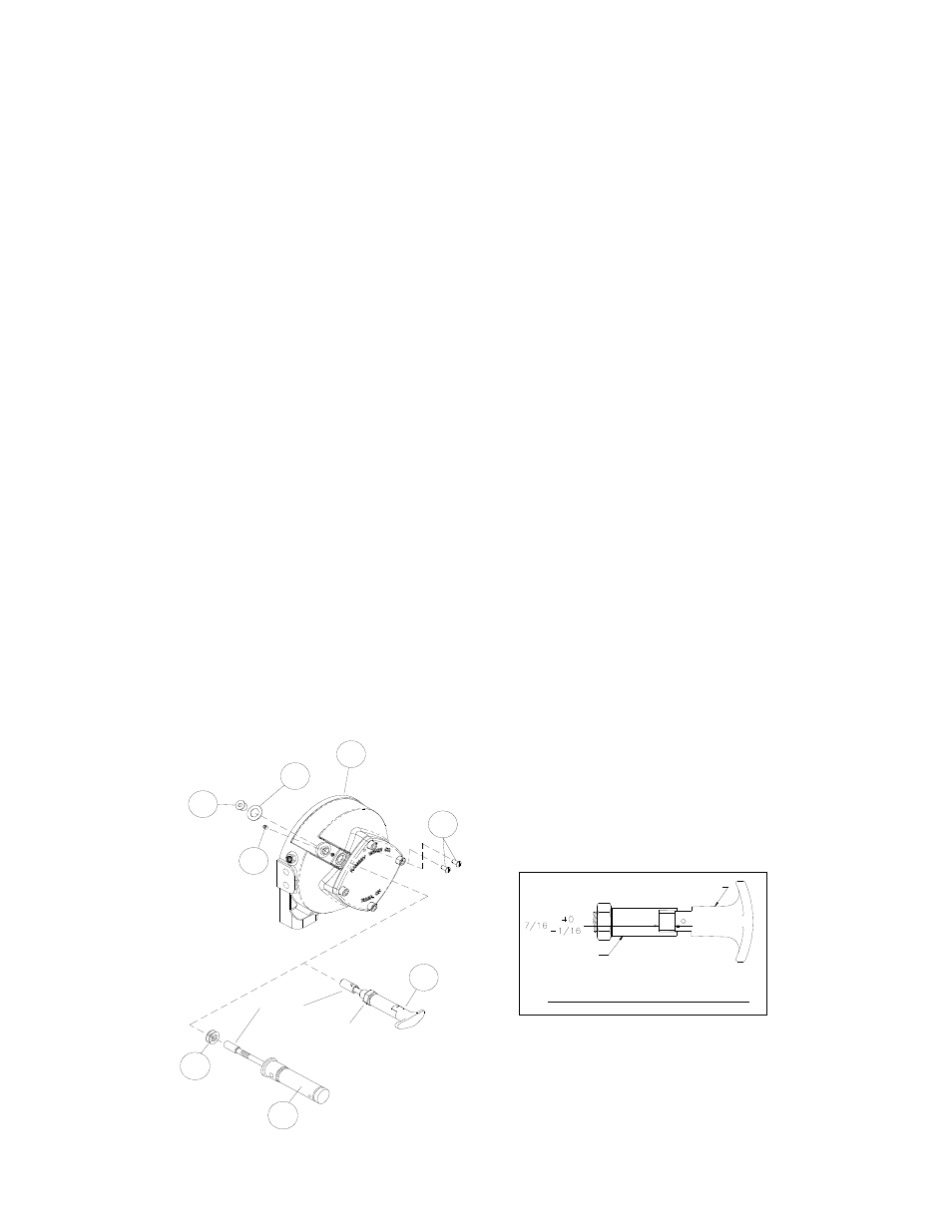
Reinstall shifter assembly with plunger, jam nut, and handle positioned in gear housing as shown below.
Thread assembly (with handle engaged in cylinder slot) into the gear housing. Pull drum toward the gear
end bearing housing to remove play. Hold drum in position and continue threading the shifter assembly in
until the gap between the end of the handle and cylinder is 7/16 +0/ -1/16 inch and handle is in the horizontal
position (see below). Note: This gap will vary with drum endplay. With the drum pulled against the motor end
housing, the gap should be 3/8 inch.
Lightly tighten jam nut. Rotate drum until handle snaps fully into the engaged position. Pull handle out and
rotate 90°. Verify that drum can be rotated freely (at least one full revolution) with clutch shifter at the DIS-
ENGAGED position. Securely tighten jam nut while holding the handle. Tighten setscrew (item #23) se-
curely. Re-check clutch operation as described on page 4.
AIR CYLINDER SHIFTER ASSEMBLY
Loosen set screw (item #23) to remove shifter assembly (item #6). To reinstall, place 1 or 2 shims (items
#48) over plunger and thread shifter assembly into gear end housing. Add or remove shims to orient ports
for pneumatic connections. Ports should point down (below horizontal). Tighten setscrew. Check for clutch
operation as described on page 4.
51
43
12
23
5
20
48
6
CYLINDER
HANDLE (HORIZONTAL)
MANUAL CLUTCH ADJUSTMENT
MANUAL CLUTCH
SHIFTER
AIR-CYLINDER
CLUTCH SHIFTER
PLUNGER
JAM NUT