Installation of the portability kit – Powermate PM0612023 User Manual
Page 11
Tools Required:
Hammer, 1/2” wrench, ratchet with a 1/2” socket, and
wood blocks.
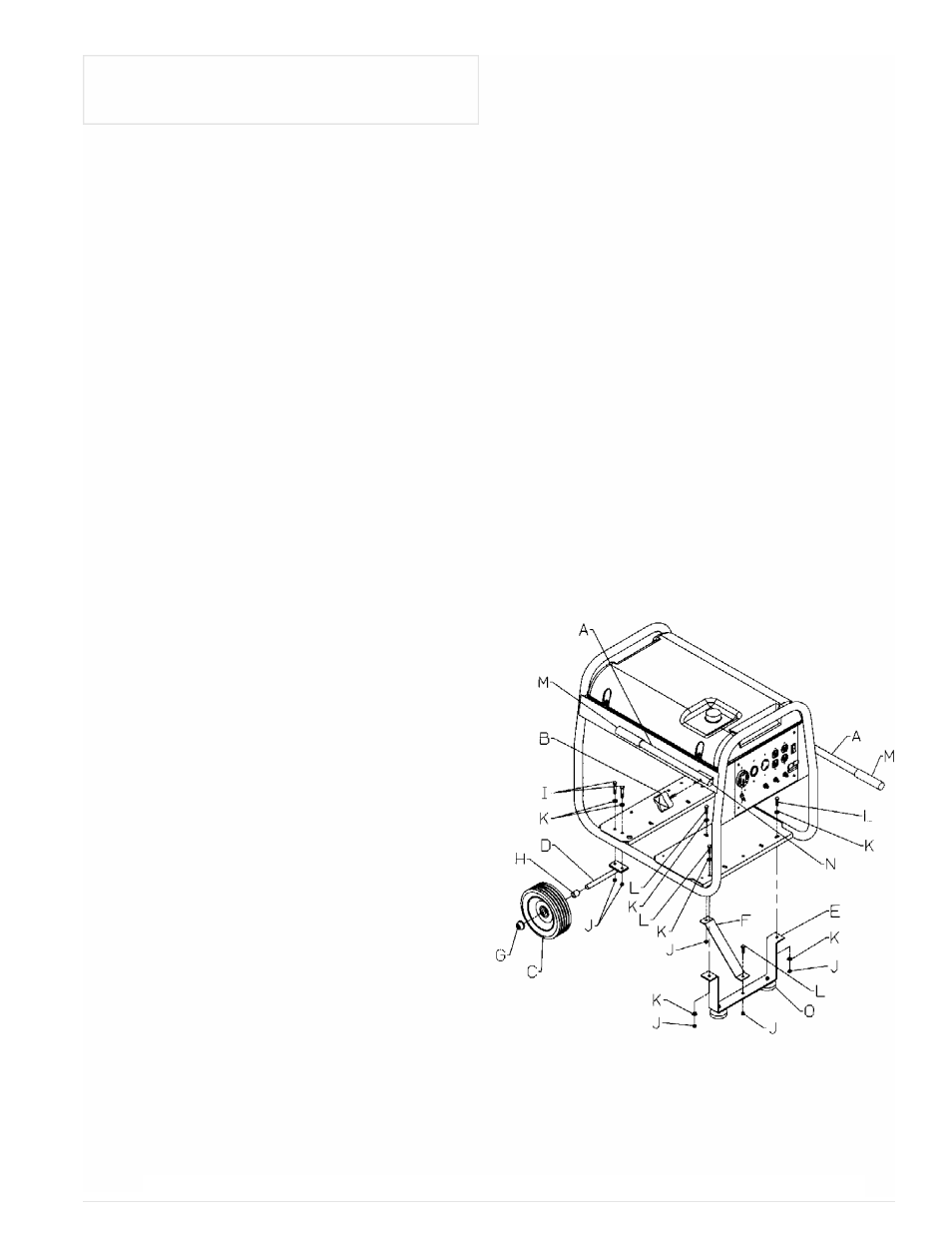
Refer to the drawing for proper alignment of Foot bracket
and Wheel brackets.
Parts List
A
Handle
0056240
B
Knob
0062177
C
Wheel
0056236
D
Wheel Bracket
0056406
E
Foot Bracket
0056237
F
Foot Bracket Strap
0056409
G
Axle Cap
0056444
H
Wheel Spacer
0056445
I
Bolt 5/16-18X1.75”
Note A
J
Nyloc Nut 5/16
Note A
K
Flat Washer 5/16
Note A
L
Bolt 5/16-18X1”
Note A
M
Handle Grip
0056239
N
Plastic Cap
0056030.01
O
Rubber Foot
0008433
Note A: These are standard parts available at your
local hardware store.
Wheel Bracket & Wheel Installation
1. Block up end of generator , about 8” high, opposite
the fuel tank cap to install wheels and wheel bracket
assy.
2. Add 5/16 washer to the 1 3/4” bolts and insert
bolts/washers through the holes located in the base pan
of the carrier.
3. Place the wheel bracket through the bolts and add a
5/16 nyloc nut and tighten securely. (On the bottom side
of the pan in-between the holes will be a 1” square
brace, the wheel bracket will set on this brace).
4. Add wheel spacer to the axle.
5. Slide the wheel onto the axle until it is snug agaist the
spacer. The wheel is on correctly if there is
approximately a 1/2” gap between the carier tubing and
the side of the wheel . If it is less then 1/2” from the
carrier, turn the wheel over and reinstall. Align the
wheels parallel to the carrier tubing and tighten nuts
securly. To align correctly, the bolts holding the wheel
bracket may have to be loosened.
6. With a hammer, add the plastic cap on end of axle.
7. Repeat above instrucitons for the remaining wheel.
Foot bracket Installation
1. Block up opposite end of. the unit, about 8” high.
2. Add 5/16 washer to 1” bolts and place through holes
in the base pan.
3. Add foot bracket assy to bolts, add 5/16 nyloc nuts
and tighten securely.
4. Add support bracket from foot bracket to the base
pan. Secure in place with 1” bolts, washers and 5/16
nyloc nuts.
Handle Installation
1. Insert the threaded end of the knobs through the
holes in the handles.
2. Line up handle with knob to the side of the carrier and
place the threads into the holes at the handle location on
the carrier. Tighten securely.
CAUTION, DO NOT OVER TIGHTEN.
Note: Handles can be placed in both directions. Along
the carrier rails for storage and extended to move the
unit.
11
English
INSTALLATION OF THE
PORTABILITY KIT