Maintenance, Overload protection, Opera t orʼs manual – Lincoln Electric IMt10100 WIRE FEEDER WELDER 140_180 User Manual
Page 25
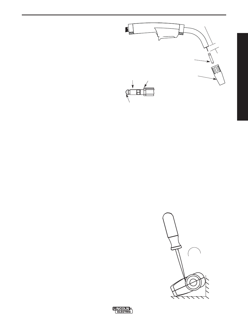
1-1/4”(31.8 mm)
Liner Trim Length
Gas Diffuser
Gas Nozzle or
Gasless Nozzle
D-2
MAINTENANCE
D-2
WIRE FEEDER WELDERS (140, 180 MODELS)
OVERLOAD PROTECTION
Output Overload
The WIRE FEEDER WELDERS (140, 180 MODELS)
is equipped with a circuit breaker and a thermostat
which protects the machine from damage if maximum
output is exceeded. The circuit breaker button will
extend out when tripped. The circuit breaker must be
manually reset.
Thermal Protection
The WIRE FEEDER WELDERS (140, 180 MODELS)
has a rated output duty cycle as defined in the
Technical Specification page. If the duty cycle is
exceeded, a thermal protector will shut off the output
until the machine cools to a reasonable operating tem-
perature. This is an automatic function of the WIRE
FEEDER WELDERS (140, 180 MODELS) and does
not require user intervention. The fan continues to run
during cooling.
Electronic Wire Drive Motor Protection
The WIRE FEEDER WELDERS (140, 180 MODELS)
has built-in protection for wire drive motor overload.
Set Screw
Brass Cable
Connector
Liner Assembly
(Liner bushing to be sealed tight
against brass cable connector)
FIGURE D.2
Liner trim length
CHANGING LINER
NOTICE: The variation in cable lengths prevents the
interchangeability of liners. Once a liner has been cut
for a particular gun, it should not be installed in anoth-
er gun unless it can meet the liner cutoff length
requirement. Refer to Figure D.2.
1. Remove the gas nozzle from the gun by unscrew-
ing counter-clockwise.
2. Remove the existing contact tip from the gun by
unscrewing counter-clockwise.
3. Remove the gas diffuser from the gun tube by
unscrewing counter-clockwise.
4. Lay the gun and cable out straight on a flat surface.
Loosen the set screw located in the brass connec-
tor at the wire feeder end of the cable. Pull the liner
out of the cable.
5. Insert a new untrimmed liner into the connector end
of the cable. Be sure the liner bushing is stenciled
appropriately for the wire size being used.
6. Fully seat the liner bushing into the connector.
Tighten the set screw on the brass cable connector.
At this time, the gas diffuser should not be installed
onto the end of the gun tube.
7. With the gas nozzle and diffuser removed from the
gun tube, be sure the cable is straight, and then
trim the liner to the length shown in the Figure D.2.
Remove any burrs from the end of the liner.
8. Screw the gas diffuser onto the end of the gun tube
and securely tighten.
9. Replace the contact tip and nozzle.
GUN HANDLE PARTS
The gun handle consists of two halves that are held
together with a collar on each end. To open up the
handle, turn the collars approximately 60 degrees
counter-clockwise until the collar reaches a stop. Then
pull the collar off the gun handle. If the collars are diffi-
cult to turn, position the gun handle against a corner,
place a screwdriver against the tab on the collar and
give the screwdriver a sharp blow to turn the collar
past an internal locking rib. See Figure D-3.
¢
Counter-clockwise
FIGURE D.3
OPERA
T
ORʼS MANUAL