Operation, Warning opera t orʼs manual, B-10 – Lincoln Electric IMt10100 WIRE FEEDER WELDER 140_180 User Manual
Page 19
B-10
OPERATION
B-10
WIRE FEEDER WELDERS (140, 180 MODELS)
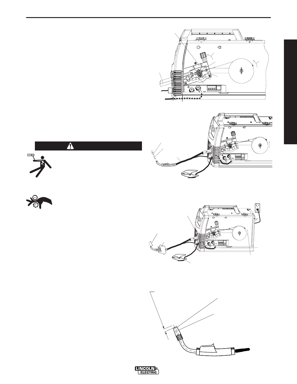
(See Figure B.16)
6. Feed the wire through the inlet liner, over the drive
roll groove, thru the outgoing guide and wire drive
outlet on the gun side.
7. Close the Pivot Arm Assembly and secure by piv-
oting the Tension Arm Assembly back to the up
position.
(See Figure B.17)
8. Remove the nozzle from the gun and contact tip
and straighten the gun out flat.
9. Turn the machine power to on and depress the
gun trigger to feed the wire through the gun liner
until the wire comes out of the threaded end of the
gun several inches. (See Figure B.18)
10. When trigger is released spool of wire should not
unwind. Adjust wire spool brake accordingly.
MOVING PARTS AND ELECTRICAL
CONTACT CAN CAUSE INJURY OR BE
FATAL.
•When the gun trigger is depressed
drive rolls, spool of wire and electrode
are ELECTRICALLY LIVE (HOT).
• Keep away from moving parts and
pinch points.
• Keep all Doors, Covers, panels and
guards securely in place.
DO NOT REMOVE OR CONCEAL
WARNING LABELS.
-----------------------------------------------------------------------
11. Install the .025”(0.6mm) contact tip.
12. Install the copper gas MIG welding nozzle to the
gun.
13. Trim the wire stickout to 3/8”(9.5mm) from the noz-
zle end. (See Figure B.19)
14. Close the case side door. The machine is now
ready to weld.
15. Read "Learn to Weld" (LTW1) that is included with
the machine or watch the "How to Weld" DVD
included with the machine.
16. Based on the thickness of the material you are
going to weld and the type and diameter of the
welding wire set the voltage and the wire feed
speed per the procedure decal attached to the
inside of the wire drive compartment door.
TENSION ARM ASSEMBLY
LOCKED IN UP POSITION
PIVOT ARM ASSEMBLY
WITH BEARING PRESSING
AGAINST DRIVE ROLL
DIRECTION
OF WIRE
DRIVE ROLL
LINER
OUTGOING GUIDE
BEARING
SLIDE WIRE
INTO GUN
CONNECTOR
SIDE
WIRE SPOOL
.025" (0.6mm)
L
-5
6 S
OLI D MI
G
WIRE SPOOL
.025" (0.6mm)
L
-56 S
OLID M
IG
REMOVED NOZZLE
REMOVED CONTACT TIP
LAY CABLE AND GUN STRAIGHTEN
IN THIS POSITION
"
%%
"
! "
" "
"
#$
"
"
INSTALL .025”(0.6mm) CONTACT TIP
INSTALL COPPER NOZZLE
TRIM WIRE
STICKOUT
3/8"(9.5mm)
from the Copper Nozzle
FIGURE B.17
FIGURE B.18
FIGURE B.19
FIGURE B.16
WARNING
OPERA
T
ORʼS MANUAL