Installation, Select suitable location, Safety precautions – Lincoln Electric IMT891 WIRE FEEDER WELDER 125, 140, 180 User Manual
Page 8: Warning
INSTALLATION
WIRE FEEDER WELDERS (125, 140, 180 MODELS)
A-2
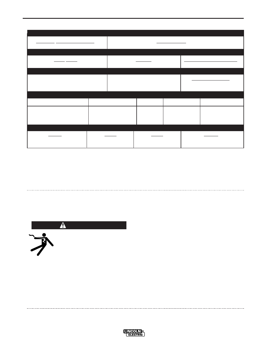
TEChNICAL SPECIFICATIONS 125 Amp units (K2479-1, K2513-1, K2696-1, K2699-1, K2785-1)
INPuT – SINGLE PhASE ONLY
RATED OuTPuT
OuTPuT
Standard Voltage/Frequency
Input Current
120 V / 60 Hz
20 Amps @ rated output
Duty Cycle
Current
Voltage at Rated Amperes
20% Duty Cycle
90 Amps
19
Welding Current Range
Maximum-Open Circuit Voltage
Wire Speed Range
30-125 Amps
33 V
50 - 500 in/min.
(1.3 - 12.7 m/min.)
Input Voltage / Frequency
Fuse or breaker Size
1,2
Input Amps
Power Cord Extension Cord
120 V 60 Hz
20 Amp
20
15 Amp, 125 V, 3 Conductor # 12 AWG
Three Prong Plug (4mm
2
) or Larger
(NEMA Type 5-15P) up to 50 ft.(15.2m)
RECOMMENDED INPuT CAbLE AND FuSE SIzES
height
Width
Depth
Weight
13.7 in
10.15 in
17.9 in
48 Ibs
347 mm
258 mm
454 mm
21.7 kg
PhYSICAL DIMENSIONS
1
If connected to a circuit protected by fuses use Time Delay Fuse marked “D”.
A-2
SELECT SuITAbLE LOCATION
Locate the welder in a dry location where there is free
circulation of clean air into the louvers in the back and
out the front of the unit. A location that minimizes the
amount of smoke and dirt drawn into the rear louvers
reduces the chance of dirt accumulation that can
block air passages and cause overheating.
STACKING
WIRE FEEDER WELDER(125, 140, 180 MODELS)
cannot be stacked.
TILTING
Each machine must be placed on a secure, level sur-
face, directly or on recommended cart. The machine
may topple over if this procedure is not followed.
Read entire installation section before starting
installation.
SAFETY PRECAuTIONS
ELECTRIC ShOCK can kill.
• Only qualified personnel should perform
this installation.
• Only personnel that have read and under-
stood the POWER MIG Operating Manual
should install and operate this equipment.
• Machine must be plugged into a receptacle
which is grounded per any national, local
or other applicable electrical codes.
• The POWER MIG power switch is to be in
the OFF (“O”) position when installing
work cable and gun and when connecting
power cord to input power.
WARNING
2
Requirements For Maximum Output
In order to utilize the maximum output capability of
the machine, a branch circuit capable of 25 amps at
120 volts, 60 Hertz is required.