Operation, Case back controls – Lincoln Electric IM10083 POWER WAVE R350 User Manual
Page 22
B-4
OPERATION
B-4
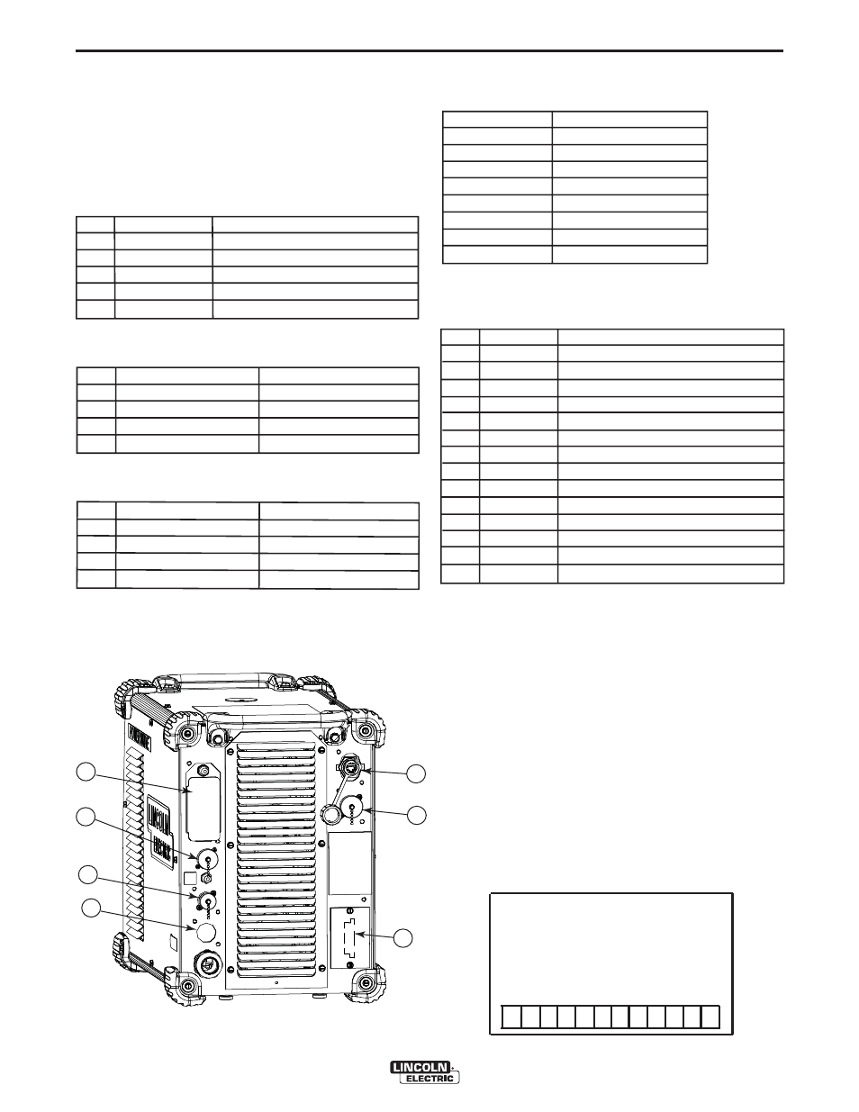
CASE BACK CONTROLS
(See Figure B.2)
1. 115V / 15A DUPLEX RECEPTACLE AND
CIRCUIT BREAKER 1 (10 AMP): Provides protec-
tion for the 115V auxiliary.
2. ARCLINK
®
RECEPTACLE AND CIRCUIT
BREAKER 2 (10 AMP):
Pin
Lead
Function
A
53A / 53B
Communication Bus L
B
54A / 54B
Communication Bus H
C
67A / 67B
Electrode Voltage Sense
D
52A / 52B
+40V DC
E
51A / 51B
0 VDC
3. SYNC-TANDEM CONNECTOR (4 PIN – MS
STYLE):
Pin
Lead Function
A
WHITE
“Ready” H
B
BLACK/RED
“Ready” L
C
GREEN
“Kill” H
D
BLACK/GREEN
“Kill” L
4. OPTIONAL DEVICENET CONNECTOR (5 PIN –
SEALED MINI STYLE):
Pin
Lead Function
2
894
+24 VDC DeviceNet
3
893
Common DeviceNet
4
892
DeviceNet H
5
891
DeviceNet L
5. ETHERNET CONNECTOR (RJ-45): Used for
ArcLink
®
XT communication. Also used for diag-
nostics and reprogramming the Power Wave R350.
Pin
Function
1
Transmit +
2
Transmit -
3
Receive +
4
---
5
---
6
Receive -
7
---
8
---
6. WIRE FEEDER RECEPTACLE (14-PIN): For con-
nection to the Auto Drive 4R100/4R220 and
PF10R series wire feeders.
Pin
Lead
Function
A
539
Motor +
B
541
Motor -
C
521
Solenoid +
D
522
Solenoid Common
E
845
Tach 2A differential signal
F
847
Single Tach input
G
841
+15V Tach supply
H
844
Tach common
I
Open
Reserved for future use
J
Open
Reserved for future use
K
842
Tach 1A differential signal
L
843
Tach 1B differential signal
M
846
Tach 2B differential signal
N
67G
Electrode Voltage Sense
7. OPTIONAL EXTERNAL I/O CONNECTOR:
Terminal Strip for making simple input signal connec-
tions. (See Figure B.2a)
The terminal strip is divided into three groups:
Group #1 - TRIGGER
Group #2 - FEED FORWARD/REVERSE
Group #3 - SHUTDOWN INPUTS
When the Power Wave S350(CE) is controlled via
DeviceNet, the “TRIGGER” and “Feed” groups can
interfere with the welding sequence and should not be
used.
All inputs use "normally open" logic except the shut-
down group. The shutdown inputs use "normally
closed" logic, and are always enabled. Unused shut-
downs must be tied to the +15V supply for the shut-
down group. Machines are shipped from the factory
with jumpers installed on both shutdown inputs.
POWER WAVE
®
R350
1
2
3
4
5
6
7
FIGURE B.2
FIGURE B.2a
1
2
3
4
5
6
7
8
9
10
11
12
+15VDC - Group #1
T
rigger
Dual Procedure
+15VDC - Group #2
Feed Forward
2/4 Step
Gas Purge
Feed Reverse
+15VDC - Group #3
Shutdown 1 Input
Shutdown 2 Input