Operation, Welder/generator controls, Engine operation – Lincoln Electric IM10073 OUTBACK 145 User Manual
Page 18: Controls and settings
1
8
2
7
6
5
9
3 or 4
B-4
OPERATION
B-4
OUTBACK™ 145
®]
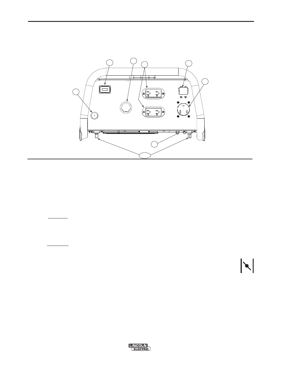
CONTROLS AND SETTINGS
All welder/generator controls are located on the Output Control Panel.
Gasoline engine controls are mounted on the engine. See Figure B.1 and the figures in engine operation section.
WELDER/GENERATOR CONTROLS
See Figure B.1 for the location of the following features:
1. CURRENT CONTROL DIAL: Adjusts continuous cur-
rent output. The amperages on the dial correspond to
the approximate amperages needed for specific
Lincoln welding electrodes.
2. 20 AMP CIRCUIT BREAKER: Provides overload cur-
rent protection for the 120 Volt and 240 Volt
Receptacles
3. WELD POSITIVE OUTPUT TERMINAL: Pro vides the
connection point for either the electrode holder or the
work cable. (Because the OUTBACK™ 145 is a DC
output machine, either output terminal can be used for
either cable.)
4. WELD NEGATIVE OUTPUT TERMINAL: Provides the
connection point for either the electrode holder or the
work cable. (Because the OUTBACK™145 is a DC
output machine, either output terminal can be used for
either cable.)
5. GROUND STUD: Provides a connection point for con-
necting the machine case to earth ground for the
safest grounding procedure.
6. 240 VOLT RECEPTACLE: Connection point for sup-
plying 250 volt power to operate one electrical device.
7. 120 VOLT DUPLEX RECEPTACLES (2): Connection
point for supplying 120 volt power to operate one or
has run for maintenance purposes.
OUTPUT PANEL CONTROLS
FIGURE B.1
8. HOUR METER: Records the time that the engine has
run for maintenance purposes.
9. CHOKE LEVER: (See Engine Operation Section)
ENGINE OPERATION
Starting/Shutdown Instructions
Be sure all Pre-Operation Engine Service has been
performed. Also, Read owners manual before starting
for the first time. (See INSTALLATION section)
NOTE: Remove all loads connected to the AC power
receptacles before starting the gasoline
engine. Put the “ON/OFF” Switch in the
“ON”(I) position.
FOR A “COLD” ENGINE:
Open the fuel shutoff valve.
Place the choke lever in the “CHOKE” position.
Pull slightly on the recoil starter handle until resistance
is felt.
Pull the cord rapidly.
If the engine does not start, open the choke slightly
and pull the starter cord rapidly again.