Troubleshooting, 7troubleshooting – Lincoln Electric IM10070 Control Box CB-WCS User Manual
Page 14
CONTROL BOX CB-WCS
6
Observe all safety guidelines detailed throughout this
instruction manual.
This troubleshooting guide is provided to help you locate
and repair possible machine malfunctions. Simply follow the
four-step procedure listed below.
Step 1: Symptom
The first column labeled “Symptom” describes possible
symptoms that the machine may exhibit. Find the listing that
best describes the symptoms that the machine is exhibiting.
Step 2: Locate Problem
The second column “Problem” describes the possible
consequences of the found symptom.
Step 3: Possible Cause
The third column labeled “Possible cause” lists the obvious
external possibilities that may contribute to the machine
symptom.
Step 4: Solution
The fourth column labeled “Solution” provides a course of
action for the possible cause. Generally it states to contact
your local Lincoln Authorized Field Service Facility.
7
TROUBLESHOOTING
A number problems in the checklist below can also
be caused by defects in the connected equipment.
This manual mainly deals with problems and
solutions directly related to the product itself.
WARNING!
Service and repair should only be performed by
Lincoln Electric Factory Trained Personnel.
Unauthorized repairs performed on this equipment
may result in danger to the technician and machine
operator and will invalidate your factory warranty.
For your safety and to avoid electrical shock,
please observe all safety notes and precautions
detailed throughout this instruction manual.
CAUTION!
If for any reason you do not understand the test
procedures or are unable to safely perform the
tests and repairs, contact your Local Lincoln
Authorized Field Service Facility for technical
troubleshooting assitance before you proceed.
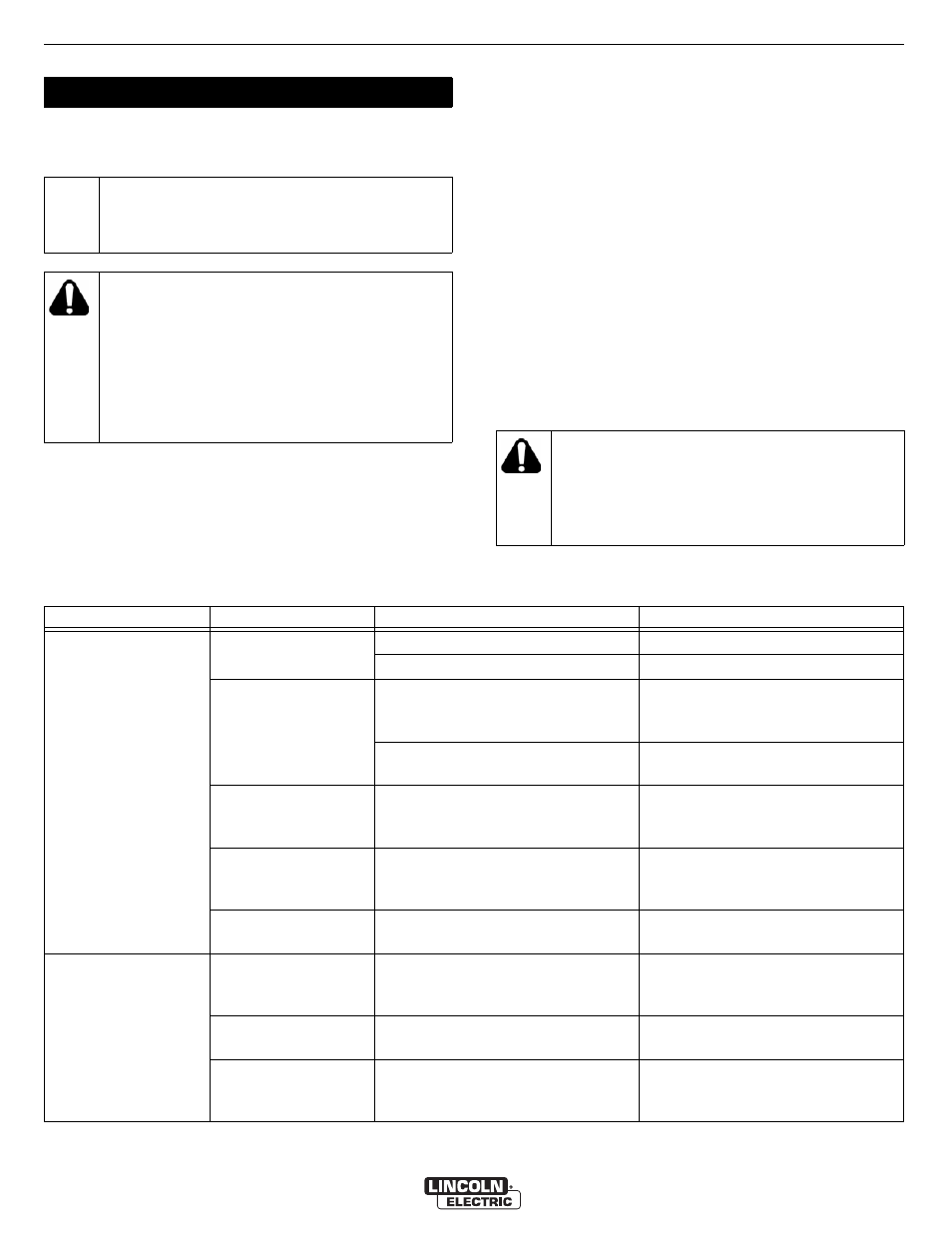
Table 1: Troubleshooting guide
Symptom
Problem
Possible Cause
Solution
No extraction when
welding starts.
Fan motor does not
start.
Thermal breaker activated.
Reset thermal breaker.
No power connected to the CB-WCS. Check power supply.
Sensor of WCS not
activated.
Sensor defective.
Check sensor function with a small
magnet. Red LED should lit on the
sensor.
Sensor not connected to the ground
cable of the welding machine.
Connect sensor to the ground cable
of the welding machine.
Sensor
malfunctioning.
Sensor broken.
Check sensor input on circuit board.
Input LED should be lit when the
sensor LED is activated
Power supply failing.
Fuse in CB-WCS broken.
Check fuse and try to determine why
the fuse blew (e.g. short circuit) and
repair.
Delay timer.
Start delay timer activated.
Please see if you want the start delay
timer to be active.
Fan keeps running
without welding
activities.
Sensor.
Sensor defective.
Check sensor function with a small
magnet. Red LED should lit on the
sensor.
Delay timer.
Stop delay timer activated (0-5
minutes).
Please see if you want the stop delay
timer to be active.
Arc sensor in use.
AST has its own delay time with a
minimum of 12 seconds stop delay
and a maximum of 2 minutes.
See if you need to change the delay
time in the AST sensor.