3 automatic start/stop device (wcs) (“wcs”), 4 work lamp (wl) and/or arc sensor (ast) (“wcs”), 4 adjustment – Lincoln Electric IM10070 Control Box CB-WCS User Manual
Page 13: 1 start delay, 2 stop delay, Operation, Maintenance, Adjustment, 6 start delay 4.4.7 stop delay, 5operation 6 maintenance
CONTROL BOX CB-WCS
5
5)
Tighten the cap nut.
4.3.3 Automatic start/stop device (WCS) (“WCS”)
7)
Feed the supply cable of the WCS through the cable
gland (“WCS”) and connect the cable in accordance
with the also supplied electric diagram.
8)
Tighten the cap nut.
4.3.4 Work Lamp (WL) and/or Arc Sensor (AST)
(“WCS”)
9)
Feed the supply cable (NCW 11) through the cable
gland (“WCS”) and connect the cable to the timer PC
board in accordance with the also supplied electric
diagram.
10) Tighten the cap nut.
If applicable:
4.3.5 Stationary welding fume extractor (Statiflex 400-
MS) (“FILTER”)
11) Feed the suply cable through the cable gland
(“FILTER”) and connect the cable as described in the
corresponding manual.
12) Tighten the cap nut.
Use Fig. 4.1 for steps 13
13) Apply the cover (D) and fix it by the mounting screws
(C).
4.4 Adjustment
The standard start delay and the standard stop delay of the
extraction fan(s) are 0 seconds. This means that the
connected fan will immediately start running when the
welding starts and will stop immediately after the (last)
welder is finished. If desired, these pre-set times can be
adjusted by changing the settings of the timer PC board (Fig.
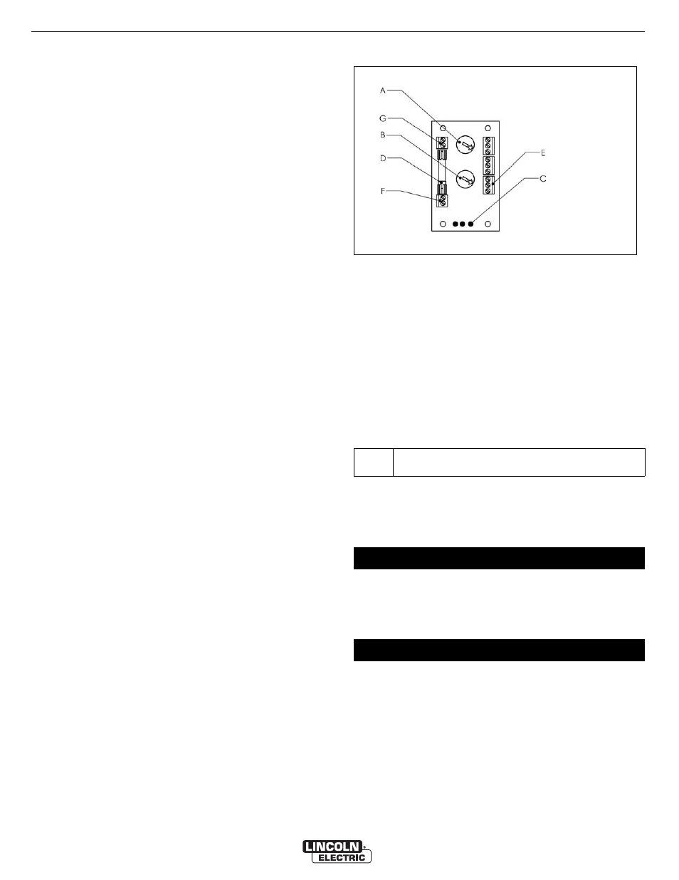
4.2). The timer PC board consists of the following
components:
A Potmeter 1 (start delay)
B Potmeter 2 (stop delay)
C Status leds
D Fuse 2A
E Connection WCS, AST, Filter
F Connection 24 VAC
G Relay contact
Fig. 4.2: Timer PC board
4.4.1 Start delay
The start delay can be set from 0 to 5 seconds (standard 0
seconds). To adjust the start delay, proceed as follows.
• Adjust Potmeter 1 (Fig. 4.2A) to the desired number of
seconds.
4.4.2 Stop delay
The stop delay can be set from 0 to 300 seconds (standard
0 seconds). To adjust the stop delay, proceed as follows.
• Adjust Potmeter 2 (Fig. 4.2B) to the desired number of
seconds.
When setting the installation, the functioning of the timer PC
board can be checked by the status leds Power, Input and
Output (Fig. 4.2C) on the timer PC board.
By applying the weldling cable sensor WCS to the ground
cable of a welding machine, the CB-WCS functions fully
automatically.
The CB-WCS does not require any specific maintenance.
In most cases, a stop delay of 20 seconds will be
sufficient.
5
OPERATION
6
MAINTENANCE