Installation, Paralleling diagram, A-7 control cable connections – Lincoln Electric IM10132 FLEXTEC 650 User Manual
Page 13: Paralleling
A-7
INSTALLATION
FLEXTEC™ 650
A-7
CONTROL CABLE CONNECTIONS
General Guidelines
Genuine Lincoln control cables should be used at all
times (except where noted otherwise). Lincoln cables
are specifically designed for the communication and
power needs of the FLEXTEC™ 650. Most are
designed to be connected end to end for ease of
extension. Generally, it is recommended that the total
length not exceed 100 feet (30.5 m). The use of non-
standard cables, especially in lengths greater than 25
feet, can lead to communication problems (system
shutdowns), poor motor acceleration (poor arc start-
ing), and low wire driving force (wire feeding prob-
lems). Always use the shortest length of control cable
possible, and DO NOT coil excess cable.
Regarding cable placement, best results will be
obtained when control cables are routed separate
from the weld cables. This minimizes the possibility of
interference between the high currents flowing
through the weld cables, and the low level signals in
the control cables.
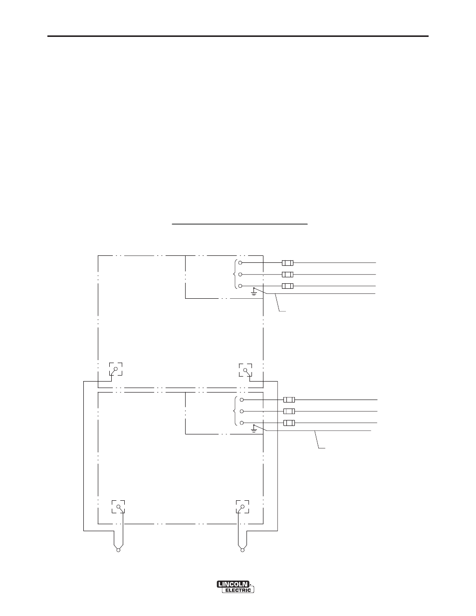
PARALLELING
FLEXTEC™ 650 power sources may be paralleled for
increased output requirements. No kit is required for
paralleling of FLEXTEC™ 650 power sources. The
FLEXTEC™ 650 can only be paralleled for constant
current processes (mode switch must be in the SMAW
position). Connect the power sources as shown, and
set the output control of each power source to one
half of the desired arc current. (See Figure A.3)
POSITIVE
AT W
WORK P
PIECE
POSITIVE
AT W
WORK P
PIECE
POSITIVE
A A
NEGATIVE
VE
W
W
PARALLELING DIAGRAM
V
U
U
IIN
NP
PU
UT
T
T
TE
ER
RM
MIIN
NAL
AL
V
V
W
W
IIN
NP
PU
UT
T L
LIIN
NES
ES
A A
N
NE
EG
GA
AT
TIIVE
VE
TO G
GROUN
UND
ELECTRICAL C
CODE
PE
PER N
NATIONAL
U
GND
N
NE
EG
GA
AT
TIIVE
VE
T
TO G
GROUN
UND
G
GND
PER N
NATIO
ONAL
ELECTRICAL C
CODE
BLOCK
F
FL
LE
EX
XT
TE
EC
C 6
65
50
0
((M
MA
AC
CH
HIIN
NE
E #1
#1))
F
FL
LE
EX
XT
TE
EC
C 6
65
50
0
((M
MA
AC
CH
HIIN
NE
E #2
#2))
IIN
NP
PU
UT
T
T
TE
ER
RM
MIIN
NAL
AL
B
BL
LO
OC
CK
K
W
W
V
U
U
V
V
W
W
IIN
NP
PU
UT
T L
LIIN
NES
ES
U
U
FIGURE A.3