Step 7: cabling, Step 8: so-dimm installation, Step 9: wall-mount plates installation – IEI Integration EBC-2102 User Manual
Page 5
EBC-2102/2102W QIG IEI Technology Corp. Page 5
STEP 7: CABLING
There are power button with LED and ports on the front
panel and rear panel of the EBC-2102/2102W chassis.
They are:
o
1 x Power button with LED
o
1 x 12 V DC power input jack
o
1 x Parallel port connector
o
3 x Audio jacks (line-in, line-out, mic-in)
o
4 x USB ports
o
3 x RS-232 serial ports (DB-9)
These components are all connected to the motherboard
with cables. To correctly connect these cables, please refer
to the user manual that came with the motherboard. The
chassis cables and the corresponding on-board connectors
are listed below.
Chassis Cable
Label Description
Power Button with
LED
F_PANEL1
Front panel connector
Parallel Port
Connector
LPT1
Parallel port connector
Audio Jacks
AUDIO1
Audio connector
RS-232 Serial
Ports
COM2
COM3
COM4
Serial port connectors
USB Ports
USB0_1
USB4_5
USB connectors
Power Input
CPU12V1
12V power connector
Table 2: Cables and Connectors
STEP 8: SO-DIMM INSTALLATION
To install the SO-DIMM, please follow the steps below.
Step 1:
Locate the SO-DIMM access panel on the
bottom of the chassis. Remove the retention
screw and remove the panel.
Figure 10: SO-DIMM Access Panel Retention Screw
Step 2:
Locate the SO-DIMM socket on the motherboard.
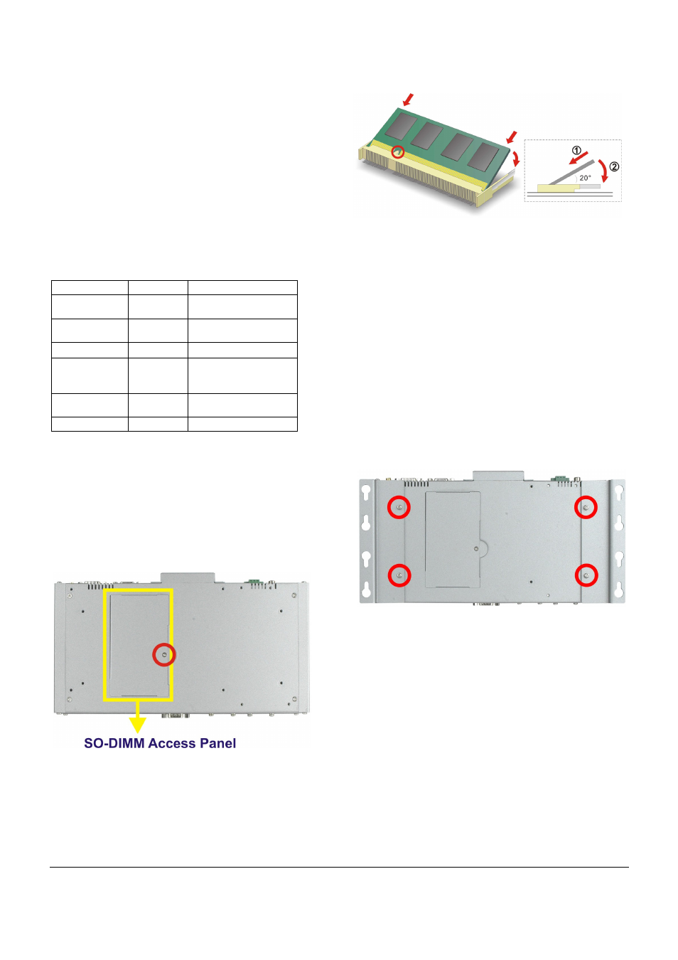
Step 3:
Align the notch on the memory with the notch on
the memory socket. Push the memory in at a 20º
angle.
Step 4:
Gently push downwards and the arms clip into
place.
Figure 11: SO-DIMM Installation
Step 5:
Reinstall the SO-DIMM access panel.
STEP 9: WALL-MOUNT PLATES
INSTALLATION
Two wall-mount plates are shipped with the EBC-2102/2102W
chassis. The wall-mount plates are installed on the sides, at the
bottom of the chassis. Each plate is secured to the chassis by two
retention screws. To install the wall-mount plates, please follow the
steps below.
Step 1:
Align the retention screw holes in the wall-mount
plate with the retention screw holes on the side of
the chassis.
Step 2:
Insert two retention screws for each wall-mount
plate.
Figure 12: Wall-mount Plate Retention Screws