Installation steps, Step 1: unpack, Step 2: remove the top cover – IEI Integration EBC-2102 User Manual
Page 3: Step 3: disk drive installation
EBC-2102/2102W QIG IEI Technology Corp. Page 3
INSTALLATION STEPS
To install the EBC-2102/2102W chassis, the following installation
steps must be completed:
Step 1:
Unpack the chassis.
Step 2:
Remove the top cover.
Step 3:
Install the internal 2.5” HDD.
Step 4:
Install the system fan. (optional)
Step 5:
Install the Wi-Fi module. (optional)
Step 6:
Install the SBC (Single Board Computer).
Step 7:
Connect the cables.
Step 8:
Reinstall the top cover.
Step 9:
Install a SO-DIMM.
Step 10:
Mount the chassis. (optional)
The installation steps outlined above are described in detail below.
Please refer to the relevant section.
STEP 1: UNPACK
The EBC-2102/2102W is shipped in a plastic bag that is placed
inside a cardboard box. The items are also shipped with the chassis.
When unpacking the chassis please:
Make sure all the items listed in the PACKING LIST
section are present.
Make sure the chassis has not been damaged in any
way.
STEP 2: REMOVE THE TOP COVER
The top cover is secured to the chassis with eight retention
screws. To remove the top cover, follow the steps below.
Step 1:
Remove the eight top cover retention screws on
the chassis.
Figure 2: Top Cover Retention Screws
Step 2:
Lift the cover up gently.
STEP 3: DISK DRIVE INSTALLATION
The EBC-2102/2102W chassis has the capacity for one 2.5” internal
HDD. To install the HDD, please follow the steps below.
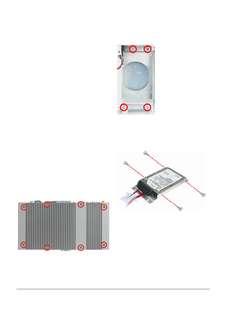
Step 1:
Remove the four HDD bracket retention screws.
Figure 3: HDD Bracket Retention Screws
Step 2:
Lift the HDD bracket out of the chassis and put it
on a flat surface.
Step 3:
Attach the HDD to the HDD bracket. Secure the
HDD with the HDD bracket by four retention
screws (Figure 4).
Figure 4: HDD Installation
Step 4:
Connect the SATA cable to the rear of the HDD
(Figure 4).
Step 5:
Install the HDD and the bracket into the chassis
with four previously removed retention screws.
Step 6:
Once the motherboard is installed to the chassis,
correctly connect the SATA signal and power
cables to the motherboard. Please refer to the
user manual that came with the motherboard for
the connector locations.