C.1 introduction, C.2 dio connector pinouts, C.3 assembly language samples – IEI Integration IMB-Q670 v2.00 User Manual
Page 170: C.3.1 enable the dio input function, Ntroduction, Onnector, Inouts, Ssembly, Anguage, Amples
IMB-Q670 Micro-ATX Motherboard
Page 156
C.1 Introduction
The DIO connector on the IMB-Q670 is interfaced to GPIO ports on the Super I/O chipset.
The DIO has both 4-bit digital inputs and 4-bit digital outputs. The digital inputs and digital
outputs are generally control signals that control the on/off circuit of external devices or
TTL devices. Data can be read or written to the selected address to enable the DIO
functions.
NOTE:
For further information, please refer to the datasheet for the Super I/O
chipset.
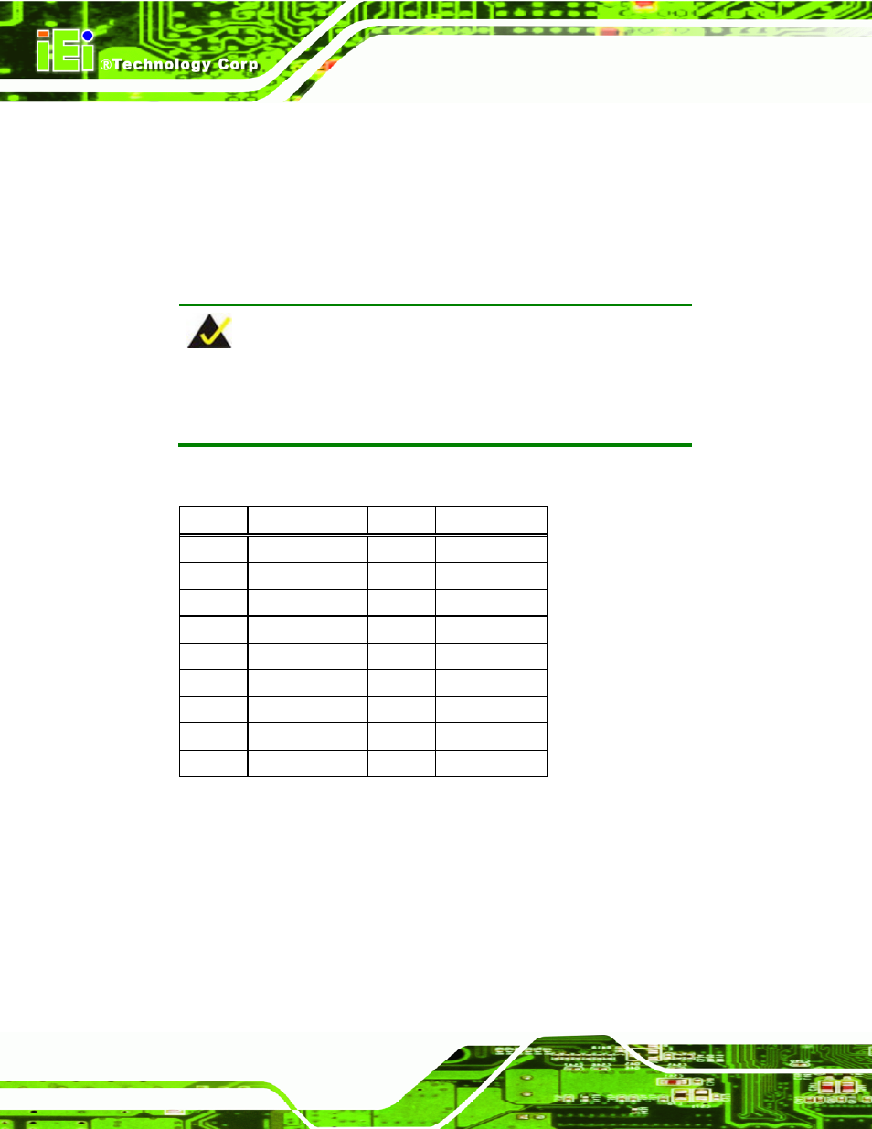
C.2 DIO Connector Pinouts
PIN NO. DESCRIPTION
PIN NO. DESCRIPTION
1
GND
2
+5V
3
D_IN0
4
D_OUT0
5
D_IN1
6
D_OUT1
7
D_IN2
8
D_OUT2
9
D_IN3
10
D_OUT3
11
D_8IN0
12
D_8OUT0
13
D_8IN1
14
D_8OUT1
15
D_8IN2
16
D_8OUT2
17
D_8IN3
18
D_8OUT3
Table 6-1: Digital I/O Connector Pinouts
C.3 Assembly Language Samples
C.3.1 Enable the DIO Input Function
The BIOS interrupt call INT 15H controls the digital I/O. An assembly program to enable
digital I/O input functions is listed below.