5 internal peripheral device connections, 1 sata drive connection, Nternal – IEI Integration KINO-AH611 User Manual
Page 64: Eripheral, Evice, Onnections, Figure 4-10: clear cmos jumper location, Table 4-3: clear cmos jumper settings
KINO-AH611
Page 52
After having done one of the above, save the changes and exit the CMOS Setup menu.
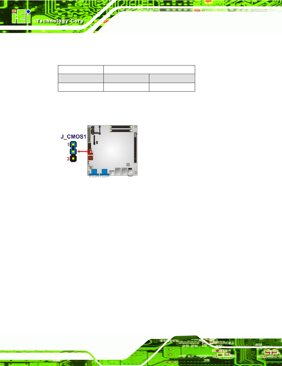
The clear CMOS jumper settings are shown in Table 4-3.
Setting
Description
Short 1-2
Normal Operation
Default
Short 2-3
Clear CMOS Setup
Table 4-3: Clear CMOS Jumper Settings
The location of the clear CMOS jumper is shown in Figure 4-10.
Figure 4-10: Clear CMOS Jumper Location
4.5 Internal Peripheral Device Connections
This section outlines the installation of peripheral devices to the on-board connectors
4.5.1 SATA Drive Connection
The KINO-AH611 is shipped with two SATA drive cables. To connect the SATA drives to
the connectors, please follow the steps below.
Step 1:
Locate the connectors. The locations of the SATA drive connectors are shown
in Chapter 3.
Step 2:
Insert the cable connector. Insert the cable connector into the on-board SATA
drive connector until it clips into place. See Figure 4-11.