Auxiliary outputs, Remote torque adjust potentiometers, Figure 5 - auxiliary indicator connections – Warner Electric CBC-750 User Manual
Page 9: Figure 6 - remote potentiometer connection
9
Warner Electric • 800-825-9050
819-0494
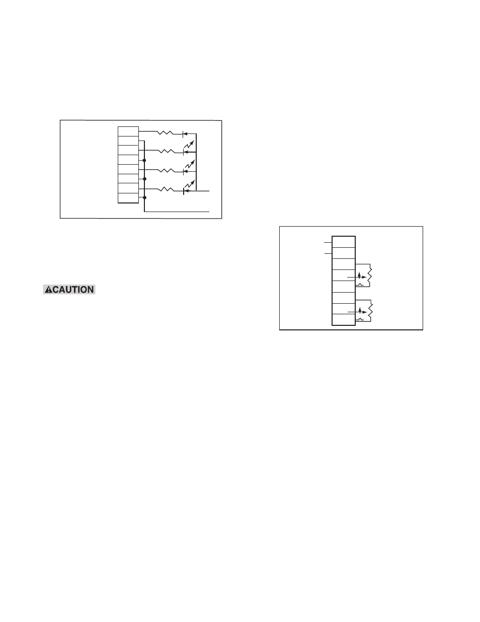
Auxiliary Outputs
Auxiliary indicator outputs are provided for optional
indicators to monitor the status of Channel 1,
Channel 2, output inhibit, and Channel 2 override.
These are opto-isolated NPN outputs.
Refer to Figure 5, below, for connections.
Figure 5 - Auxiliary Indicator Connections
Note: All resistors and LED’s shown are furnished
by the user. The power source may be either
external user furnished or the CBC-750’s
12VDC auxiliary power supply.
Do not use incandescent lamps
because their high inrush current may destroy the
opto-coupler on the CBC-750.
TB-4
CHANNEL
1
CHANNEL
2
OUTPUT INHIBIT
CHANNEL 2 OVERRIDE
FIGURE 4
(+)
+
+
+
+
(-)
24VDC MAXIMUM
-
-
-
-
1
2
3
4
5
6
7
8
-.
C
Remote torque Adjust
Potentiometers
Optional remote torque adjust inputs are provided
for torque adjust potentiometer connection.
Refer to Figure 6, below, for connections.
Note: The remote potentiometer should be wired
using shielded cable to prevent noise pick
up. The shield should be connected only
to chassis ground at terminal 7 of TB-6.
Your CBC-750 control has now been completely
wired. Before proceeding to the set-up and start-up
sections of this manual, double check to insure that
the control is properly wired.
TB -5
12VDC +
250 ma. MAX -.
CH1
REMOTE TORQUE
ADJUSTMENT
CH2
REMOTE TORQUE
ADJUSTMENT
1
2
3
4
5
6
7
8
Figure 6 - Remote Potentiometer Connection