Warner Electric CBC-200C Single User Manual
Page 7
7
Warner Electric • 800-825-9050
P-269 • 819-0407
Clutch – Electrically Released Brake Wiring
(Power on clutch/power off brake)
All electrical current must be
off when making electrical connections to
prevent injury or death which can result
from contact with live wires.
AC Input Power Connections
❑
1. Connect Earth Ground wire to Terminal 1
and tighten securely.
❑
2. Connect the Hot side of the 120 VAC line
to Terminal 2 and tighten securely.
Note: Customer supplied fuse is desirable. See
diagram for connection and sizing.
❑
3. Connect the neutral side of the 120 VAC
line to Terminal 3 and tighten securely
❑
4. For electrically released brake-clutch
arrangement proceed to the wiring section
below.
❑
1. Connect the Brake to Terminals 4 and 5.
Observe the polarity when making connec-
tions. Tighten Terminal 4 securely.
❑
2. Connect the Clutch to Terminals 7 and 8.
Tighten Terminal 7 securely.
❑
3. Connect the switching for Channel 1 to
Terminals 5 and 6. Tighten terminals securely.
❑
4. Connect the switching for Channel 2 to
Terminals 8 and 9. Tighten terminals securely.
❑
5. Set DIP Switch, SW1 for proper current
setting before applying power to the control
See INTERNAL SWITCH SETTINGS CHART
for proper DIP Switch settings.
❑
6. If external potentiometers are being used,
then proceed to the external potentiometer
wiring section. If external potentiometers are
not used, this completes the wiring of the
control.
❑
7. Double check all connections before
applying power.
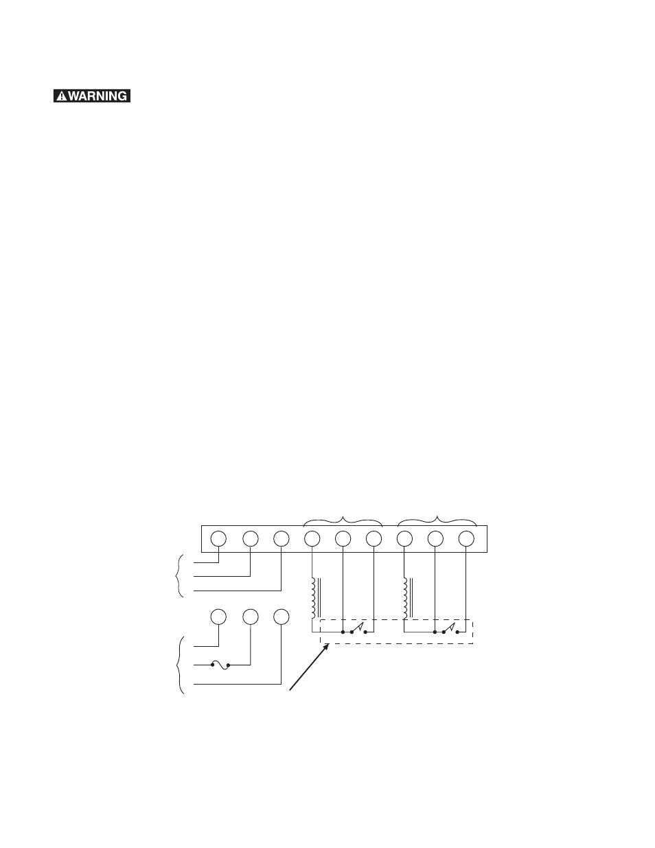
Clutch/Brake and Switch Wiring
4
5
6
7
8
9
2
3
1
2
3
1
1.5A
FUSE
or
G
H
N
120 VAC
G
H
N
120 VAC
C
lu
tc
h
B
ra
k
e
Channel 1
Channel 2
+
-
+
-
E
R
External switching by
customer,
see
specification.
Note:
If Solid-state NPN switching
is used, emitter is connected to
terminal 6 or 9 and collector is
connected to terminal 5 or 8.
Note:
Electrically released
brake must be connected to
Channel 1 Output when
CBC-200 is used.
Figure 4