WARN PullzAll Installation User Manual
Page 6
WARN INDUSTRIES * THE BASIC GUIDE TO UTILITY PULLING
11
HOW THE PULLZALL WORKS
How the PullzAll Reacts to Load
The PullzAll is rated by pulling
capacity. The maximum pulling
torque occurs when there is only
one layer of wire rope on the drum.
As the layers of wire rope on the
drum increase, the pulling power
decreases. This is the basics of
mechanical advantage.
Load Limiter
Exceeding the PullzAll capacity
will cause the load limiter to trip,
which interrupts the power to the
motor. This prevents overheating
and potential motor damage. At
90% of pulling capacity the overload
indicator turns red. When 100%
of pulling capacity is reached the
load limiter will cause the overload
indicator to fl ash red and the PullzAll
motor to stop. When this occurs,
release the load by spooling out. Do
not attempt to apply the same load
if the load limiter has tripped, as
this can be harmful to the unit. If the
load limiter fails to reset contact an
authorized service center.
If the load limiter continues to
trip, perform the following actions:
1) Reduce the weight of the load.
2) Increase the distance of the
anchor point.
3) Rig a double line pull.
For details: See “Rigging
Techniques” section in this manual.
Before using your WARN
PullzAll to pull or lift a load it is
important to understand how it
works. The major advantage
of the PullzAll is its handheld
convenience for performing
numerous recreational and work
tasks. Thinking through how you
intend to use your PullzAll now
could save you a big headache
later.
Control of Your PullzAll
The PullzAll tool has an On/
Off power switch and is controlled
by a directional switch and a
variable speed trigger control.
The directional switch
provides control of the forward and
reverse rotation of the spooling
drum. Keep tension on the wire
rope when winding in or out to
prevent “bird nesting” that can bind
and entangle the wire rope causing
damage to it and the PullzAll.
When you see the red paint on the
wire rope, do not spool out any
further. Doing so, can cause the
wire rope to spool on the drum
in the wrong direction. This can
damage the wire rope and fairlead.
The direction selection arrow
should always match the direction
of the wire rope when it is spooling
in or out.
The variable speed trigger
switch has two general modes of
operation:
1) Variable speed mode for fi ne
load positioning.
2) Full speed mode for long
distance.
WARNING
Always keep
PullzAll and
pulling load in
sight during
pulling operation.
The PullzAll
is controlled
by the variale
speed trgger
and direction
selection switch.
NOTICE
WARNING
Never spool out
past the red paint
on wire rope.
WARN INDUSTRIES * THE BASIC GUIDE TO UTILITY PULLING
12
HOW THE PULLZALL WORKS
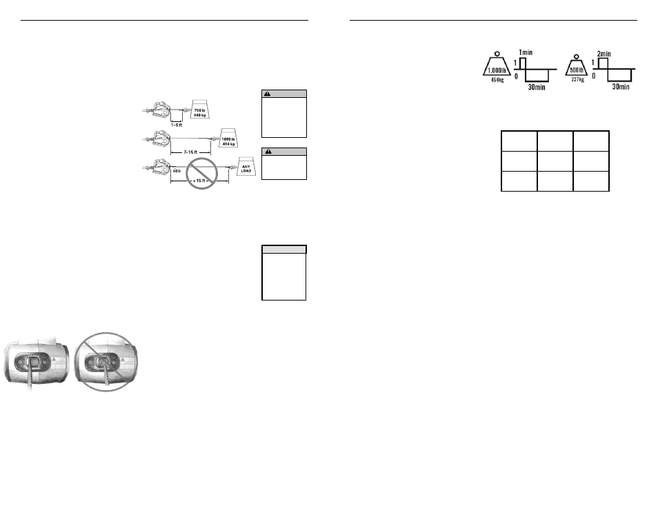
RUN TIME/DUTY CYCLE TABLE
LOAD
500 lbs.
(227 kg)
1000 lbs.
(454 kg)
RUN
TIME
2 min
1 min
COOL
TIME
30 min
30 min
PullzAll Mechanics
It is important to understand that
the longer the pull, the more heat gets
created within the motor. Spooling
out the rope also generates heat. Let
the motor cool between pulls because
prolonged use without cooling the
PullzAll will damage the motor.
Run Time/Duty Cycle
The PullzAll is rated for
intermittent duty. It should not be
operated for long periods with the
motor at low RPMs. When the motor
approaches stall speed a very rapid
heat build up occurs which may
cause motor damage. Follow the
recommended run times and cooling
times in the table shown. If the unit
does not function after it is allowed to
cool, call a Warn authorized service
center.