Vestil LM-Boom User Manual
Lm-s, Eries, Ounted
01/11
rev. 2/19/2014
LM-boom, manual
Copyright 2013 Vestil Manufacturing Corp.
LM-S
ERIES
F
ORK
-M
OUNTED
L
IFT
M
ASTER
B
OOMS
U
SE AND
M
AINTENANCE
M
ANUAL
Receiving
instructions:
After delivery, IMMEDIATELY remove the packaging from the product in a manner that preserves the packaging and
maintains the orientation of the product in the packaging; then inspect the product closely to determine whether it
sustained damage during transport. If damage is discovered during the inspection, immediately record a complete
description of the damage on the bill of lading. If the product is undamaged, discard the packaging.
NOTES:
1) Compliance with laws, regulations, codes, and non-voluntary standards enforced in the location where the product is
used is exclusively the responsibility of the owner/end-user. Before using the boom for the first time, the end-user/owner
should perform an “Initial Inspection”. (See “Initial Inspection,” p. 21).
2) VESTIL is not liable for any injury or property damage that occurs as a consequence of failing to apply either:
a) Instructions in this manual; or b) information provided on labels affixed to the product. Neither is Vestil responsible for
any consequential damages sustained as a result of failing to exercise sound judgment while assembling, installing, using
or maintaining this product.
Table of Contents
Table of Figures
Product Introduction…………………… 2
Fig. 1 LM-1T & -1NT Exploded Parts Diagrams & Parts Lists………. 5 - 8
Safety Principles……………………..... 3
Fig. 2 LM-OBT & -OBNT Exploded Parts Diagrams & Parts Lists..... 9 - 12
Safety Recommendations…………….. 3 – 4
Fig. 3 LM-HRT & -HRNT Exploded Parts Diagram & Parts Lists….. 13 - 16
Standard Design Elements………….. 4
Fig. 4 LM-EBT & -EBNT Exploded Parts Diagram & Parts Lists…… 17 - 20
Operation Instructions………………… 22 - 24 Fig. 5 LMS-(EBT & -EBNT)-46-(4k, 6k, & 8k) & Parts Lists……..…… 21
Inspections & Maintenance………….. 25 - 26 Fig. 6 Step 1 - Securely connect boom to fork truck...……………….. 24
Label placement diagram…………….. 27
Fig. 7 Step 3 - Manual adjust degree of boom extension….………… 22
Limited Warranty…………………….. 28
Fig. 8 [OBT Models] Step 4 - Boom Angle Adjustment ……………… 23
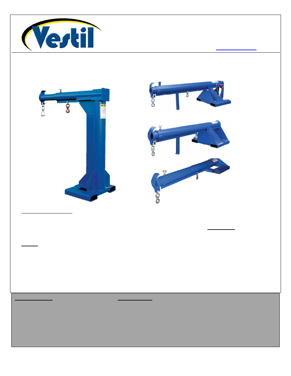
LM-HRT &
LM-HRNT
LM-EBT &
LM-EBNT
LM-1T &
LM-1NT
LM-OBT &
LM-OBNT
V
ESTIL
M
ANUFACTURING
C
ORP
.
2999 North Wayne Street, P.O. Box 507, Angola, IN 46703
Telephone: (260) 665-7586 -or- Toll Free (800) 348-0868
Fax: (260) 665-1339
www.vestilmfg.com e-mail: