Fig. 2a: side view – Vestil FM-T-DUMP User Manual
Page 6
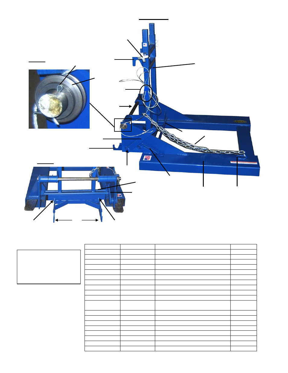
FIG. 2A: Side View
6
- 6 -
Identification
No.
Part No.
Description
Quantity
1
37-514-023
Base Frame Weldment
1
*2
37-514-022
Upright frame weldment
1
3
37-612-001
Locking Pin Weldment
1
*4
37-516-001
Can Adjustment Bracket Weldment
1
5 37-025-005
Latch
Handle
1
*6 KNOB-12
Knob
2
7 28-146-003
Tension
Spring
1
*8
03-146-001
Uni-tilt Lever Compression Spring
2
*9 37-112-025
Axle
Pin
1
10
37-027-001
2 x 5/8 Cable Pulley
1
11
65127
3/16 x 2 Cotter Pin
5
12 33444
or
33446
(Thin) 18 Ga. Machinery Bushing, or
(Thick) 12 Ga. Machinery Bushing
as
required
13
37-145-005
1/8 x 48 Cable Specialty Hardware
1
14
37-025-002
Formed Chute Release Handle
1
15
37-145-004
5/16 x 48 Chain (Specialty Hardware)
1
16
37-145-003
Wire Crimp (Specialty Hardware)
2
17
15-112-004
01 x 4-1/2 Handle Pin
1
18
37-037-021
FL-4000 Chute Latch
1
19
58777
3/16 Straight Grease Fitting
2
*20 N/A Axle
Bracket
2
7
9
5
14
2
FIG. 2C: Latch Assembly
4
FIG. 2B: Cable
Pulley
11
10
3
Latch Cross
Bar
8
20
An asterisk (*) next to a
number indicates that the
corresponding part is a
component of the “Cart-
engaging assembly”.
8
17
18
1
15
20
Quick Link