Table 2.0 dmom-100, Controls and indicators, Operating procedures dmom-100 – Vanguard DMOM-100 User Manual
Page 10
Operating Procedures
DMOM-100™
4
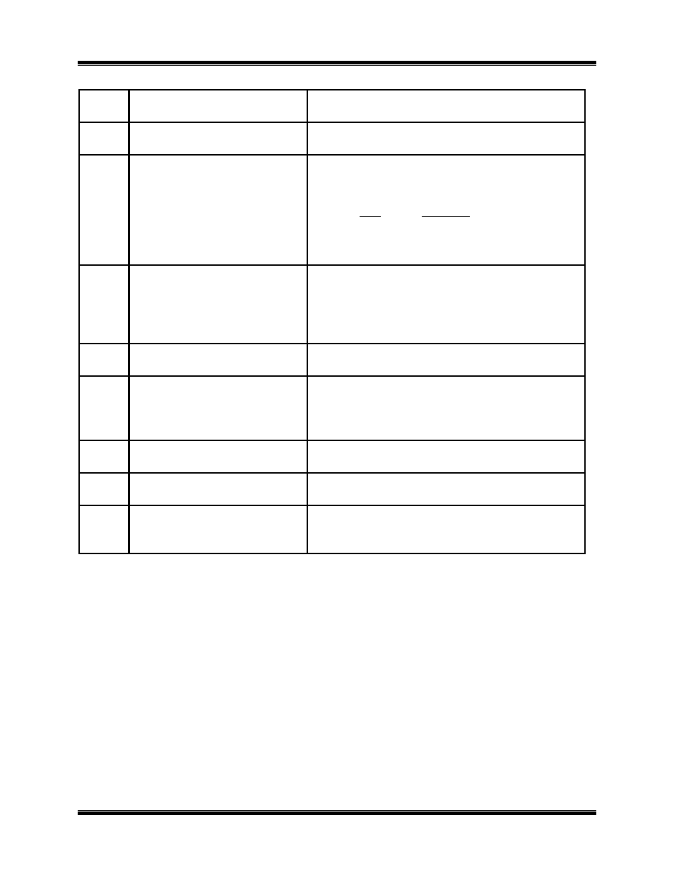
Table 2.0
DMOM-100
Controls and Indicators
Fig. 1
Index
PANEL MARKING
FUNCTIONAL DESCRIPTION
1
ON/OFF
Input power connector with third-wire safety
ground and 10A built-in circuit breaker.
2
RS-232C
Connector, 9-pin; Serial interface-port connector
(female DB type) to allow the DMOM-100
to
be controlled by an IBM-compatible PC.
PIN
SIGNAL
2
Tx
3
Rx
5 Signal Gnd
3
(no marking)
Display, back-lighted liquid crystal (LCD); 4-line
by 20-character; sunlight readable; displays test
menus (operator options), status, and test results
(See Figure 2 for operating displays of control
steps in logical flow sequence).
4
(no marking)
Built-in thermal printer; prints test result data on
2.5-inch-wide thermal paper.
5
(no overall marking; keys are
individually marked—see
Figure 1)
Operating key-pad controls; 10 alpha-numeric
keys and 6 function keys (i.e., START, STOP,
CLEAR, ENTER, & CONTRAST/PAPER
positioning
∧ & ∨).
6
HIGH CURRENT
PRESENT
Warning indicator; red LED; Lights when high
current is running through the test leads.
7
(no marking)
Voltage-sensing test-lead plug-in sockets (2), red;
reads voltage at test load.
8
(no marking)
Test-current lead plug-in sockets (2), red;
conducts up to 100 amperes through unknown
resistances.