Connect digital outputs, Connect input power, Do not switch on – TREND IQ251 User Manual
Page 5
5
IQ251 Installation Instructions TG103483 Issue 3, 8/10/08
Installation Instructions
IQ251
3.1 Installation - Mounting
(continued)
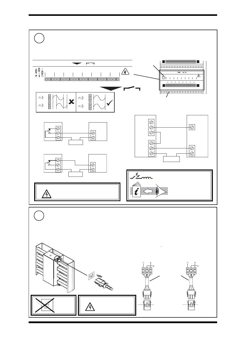
Connect Digital Outputs
13
8
D O 2
D O 3
D O 4
D O 5
D O 6
D O 7
D O 8
D O 1
C
N o N c
C
N o N c
C
N o N c
C
N o N c
C
N o N c
C
N o N c
C
N o N c
C
N o N c
C A U T I O N
H I G H V O L T A G E
M A Y B E P R E S E N T
I S O L A T E E L S E W H E R E
Digital Output Channels (DO1 to DO8)
8
D O 2
D O 3
D O 4
D O 5
D O 6
D O 7
D O 8
D O 1
C
N o N c
C
N o N c
C
N o N c
C
N o N c
C
N o N c
C
N o N c
C
N o N c
C
N o N c
/EDO/ module
earthing (grounding) bar (option)
24 Vdc (inductive) 2 A
240 Vac single phase throughout 7 A (resistive) 5 A (inductive, Cosø > = 0.4)
30 Vdc at 5 A (resistive)
For IQ251/USA, UL rating applies up to 30 V
N C
Power
NO
LOAD
n
IQ
Relay Output Arc
Suppression Installation
Instructions TG200208
WARNING: The wires may be connected to
hazardous voltages. Disconnect power
before attempting any wiring.
Drive on, load on
C
Power
LOAD
n
IQ
Drive off, load on
NC
C
NO
Actuator
IQ
NC
C
Power
NO
L
n
n + 1
2 outputs - raise/lower
R
C
If /EDO/ fitted
n+1
n
Æ a
Æ b
n+1
n
Æ a
Æ a
N C
NO
C
Cable size 0.5 to 2.5 mm
2
(20 to 14 AWG) - Cu only
Arc suppression
recommended
Connect Input Power
14
IQ251 Consumption <=100 VA
if /230
230 Vac +15 %, -10 %,
50 to 60 Hz
DO NOT
SWITCH
ON
O
I
WARNING: This apparatus must be
earthed (grounded)
using input power
connector.
if /24 VAC or /24 VDC
24 Vac +25 %, -10 %, 50 to 60 Hz
24 Vdc + 25%, -10 %, 50 to 60 Hz
IEC
A switch or circuit breaker must be included in the input
power to the unit and be in close proximity to it, and must be
clearly marked as the disconnecting device for the unit.
EJ
105383 24V
Earth
If /24VAC
24 Vac: Isolated transformer
winding supply 1 controller
only
24 Vac 24 Vac
EJ
105383 24V
Earth
If /24VDC
24 Vdc: May supply several
controllers
24 V 0 V
Earth (ground) recommended
Mat-N-Loc to
terminal adaptor
(supplied)